A power grid equipment communication data interface

A technology for communication data and power grid equipment, applied in the field of power grid, can solve problems such as poor contact, inability to engage, and difficult to transmit data effectively.

Active Publication Date: 2022-04-26
北京昊普康科技股份有限公司
View PDF9 Cites 0 Cited by
  • Summary
  • Abstract
  • Description
  • Claims
  • Application Information

AI Technical Summary

Problems solved by technology

[0003] Based on the above-mentioned inventor's discovery, there are mainly the following deficiencies in the existing ones, for example: when the communication data interface is installed in an outdoor environment, it is always exposed to the outside because the interface is open, so that the dust in the air flows It will enter the bottom edge of the slot and stay, and when the dust continues to stay and accumulate, its impurity layer will thicken, resulting in the inability to directly engage with the internal gap when the wiring is inserted, making it difficult to carry out effective data transmission due to poor contact

Method used


Image

  • A power grid equipment communication data interface
  • A power grid equipment communication data interface
  • A power grid equipment communication data interface

Examples


Embodiment 1

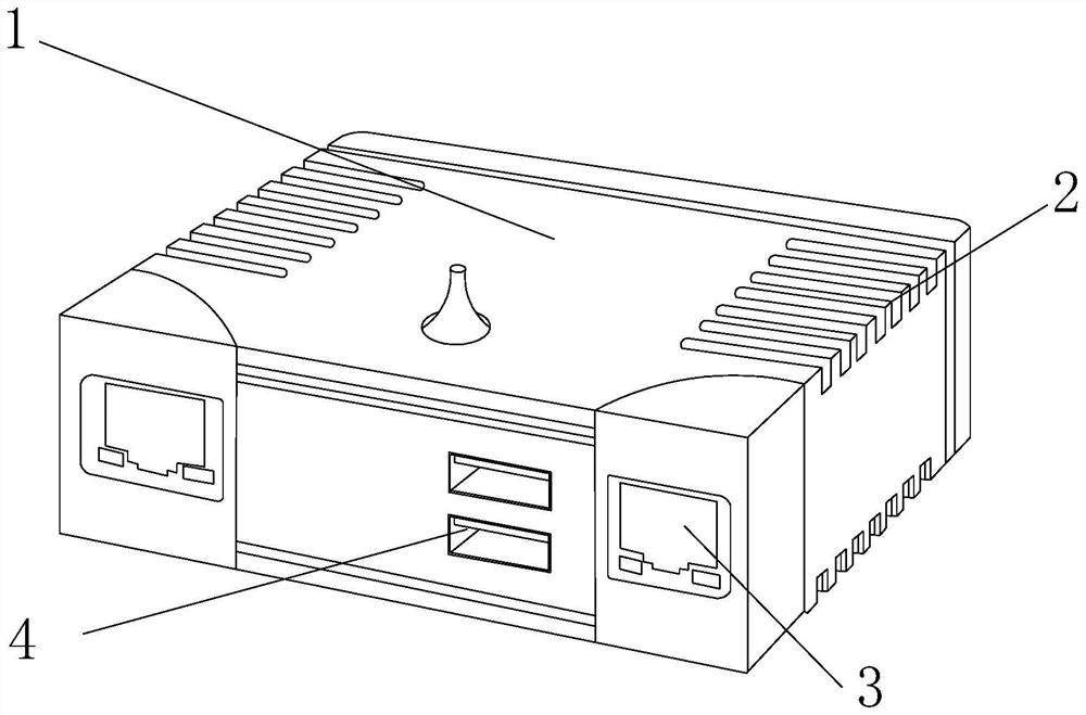
[0027] as attached figure 1 To attach Figure 5 Shown:

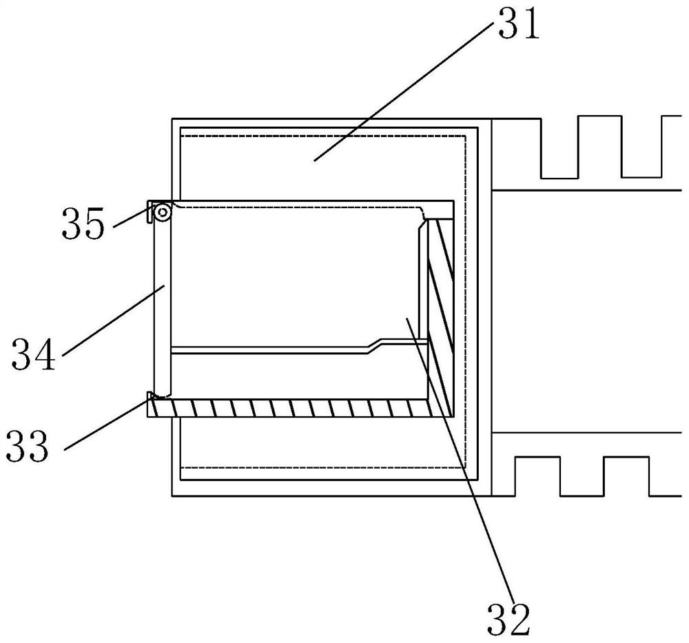
[0028] The invention provides a communication data interface for power grid equipment, the structure of which includes a data box 1, a heat dissipation hole 2, an interface 3, and a connector 4. The heat dissipation hole 2 and the data box 1 are an integrated structure, and the interface 3 is embedded It is fixedly connected to the left and right sides of the inner front end of the data box 1, the interface 3 is located at the front end of the cooling hole 2, and the connector 4 is movably engaged with the inner front end of the data box 1; the interface 3 is composed of an inner cover frame 31, a plug Groove 32, fixed plate 33, swing plate 34, limit groove 35, the slot 32 is movably engaged inside the inner cover frame 31, the fixed plate 33 is riveted to the left side of the lower end of the slot 32, the The swinging plate 34 is vertically connected to the lower end of the limiting slot 35 , the limiting slot 35 is e...

Embodiment 2

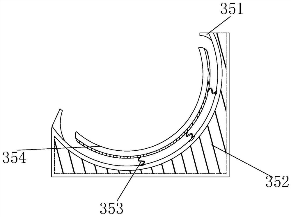
[0035] as attached Figure 6 To attach Figure 8 As shown: the interface 3 is composed of an inner cover frame 31, a slot 32, a fixed plate 33, a swing plate 34, and a limit groove 35. The slot 32 is movably engaged on the inner side of the inner cover frame 31, and the fixed The plate 33 is riveted and connected to the left side of the lower end of the slot 32, the swing plate 34 is vertically connected to the lower end of the limiting groove 35, and the limiting groove 35 is embedded and connected to the upper left side of the slot 32, and the swinging plate 34 Set on the upper end of the fixing plate 33 .

[0036] Wherein, the fixed plate 33 is composed of a contact plate 331, a top button 332, and a fixed groove 333. The contact plate 331 is embedded and connected to the upper left end of the fixed groove 333, and the top button 332 and the fixed groove 333 are an integrated structure. The 322 is in the shape of an inverted arc and the top is wrapped with a rubber layer,...


PUM


Abstract

The invention discloses a communication data interface of power grid equipment. The structure includes a data box, a heat dissipation hole, an interface, and a connector. The heat dissipation hole and the data box are an integrated structure, and the interface is embedded and connected to the left and right sides of the front end of the inner side of the data box. , the interface is located at the front end of the heat dissipation hole, the connector is movably engaged with the front end inside the data box, the limit slot is fixedly connected to the upper left side of the slot, and the swing plate is set at the top of the fixed plate. Push inward, and the sleeve is installed and wrapped on the outside of the control rod. During the ejection process, under the limitation of the control rod, the control of the fitting plate will drive the top of the swing plate to slide inward, prompting the swing plate to swing inward, and finally fit on the top depression. position, so that it can be smoothly inserted into the slot, and when pulled out, it will drive the swing plate to swing down together, closing its opening to prevent dust from flying in from the opening.

Description

technical field [0001] The invention belongs to the field of power grids, and more specifically relates to a communication data interface for power grid equipment. Background technique [0002] The whole composed of substations of various voltages and transmission and distribution lines in the power system is called the power grid, including three units of power transformation, power transmission, and power distribution, and the data interface is used as the media connection for data information transmission during communication transmission. [0003] Based on the above inventors' discovery, the existing methods mainly have the following deficiencies, such as: when the communication data interface is installed in an outdoor environment, because the interface is open and always exposed to the outside, so that the dust in the air flows It will enter and stay at the bottom edge of the slot, and when the dust continues to accumulate and accumulate, its impurity layer will thicke...

Claims


Application Information

Patent Timeline
Patent Type & Authority Patents(China)
IPC IPC(8): H01R13/52H01R13/502
CPCH01R13/5213H01R13/502
Inventor 李翠莲
Owner 北京昊普康科技股份有限公司
Why Eureka
Try Eureka