
Protection device for mining belt conveyor controller

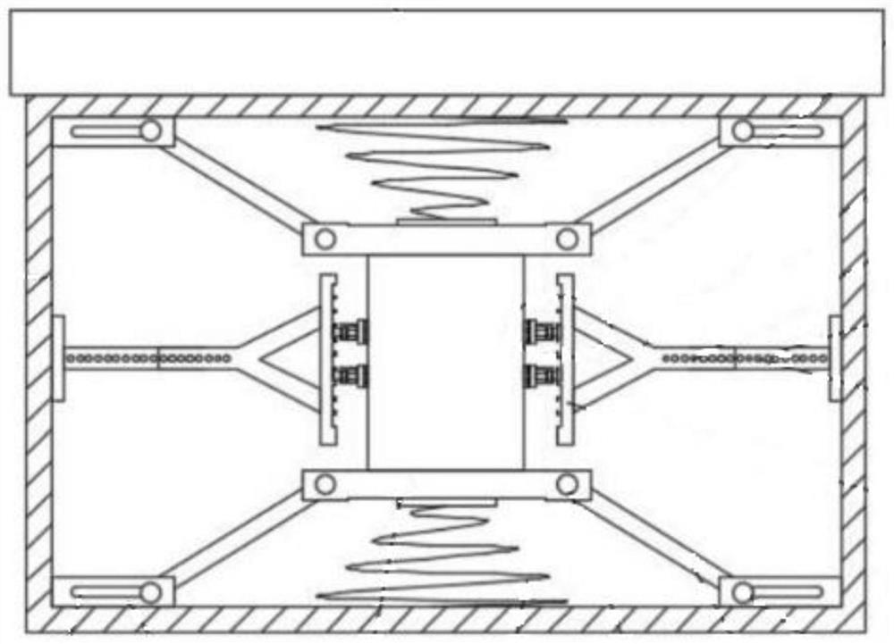
A belt conveyor and protection device technology, applied in the direction of conveyor control devices, conveyor objects, transportation and packaging, etc., can solve problems such as water ingress, controller failure, and poor contact of components, so as to improve the conduction rate, The effect of avoiding equipment damage

Pending Publication Date: 2022-04-19
HUAINAN WANTAI ELECTRONICS
View PDF1 Cites 0 Cited by
  • Summary
  • Abstract
  • Description
  • Claims
  • Application Information

AI Technical Summary

Problems solved by technology

[0004] Due to the harsh working environment of the existing mine belt conveyor controller protection device, it is often required to be hoisted during transportation so that it can be installed to a designated location in the mine conveniently and quickly. However, during the hoisting process Due to the lack of attitude adjustment mechanism of the protection device during hoisting, the control is always in a tilted state during the hoisting process and cannot be kept in a horizontal state. Small liquid droplets in the surrounding environment are very easy to enter the controller, causing the controller to malfunction and fail. The existing protection device for the controller of the mine belt conveyor often cannot quickly dissipate heat in the process of protecting the controller, often due to the need to Water ingress due to heat dissipation, and the existing protection device cannot enable the controller to be used when there is water on the ground in the mine

Method used


Image

  • Protection device for mining belt conveyor controller
  • Protection device for mining belt conveyor controller
  • Protection device for mining belt conveyor controller

Examples


Embodiment Construction

[0031] In order to further explain the technical means and effects of the present invention to achieve the intended purpose of the invention, the specific implementation, structure, features and effects of the present invention will be described in detail below in conjunction with the accompanying drawings and preferred embodiments.

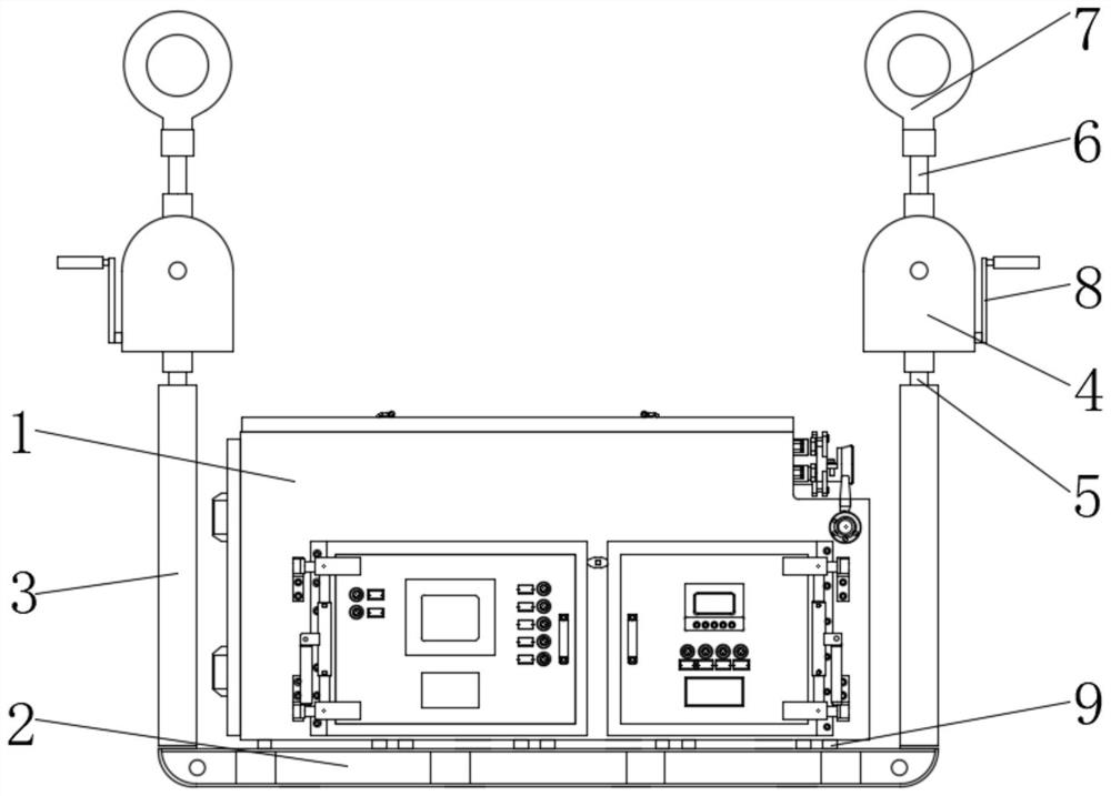
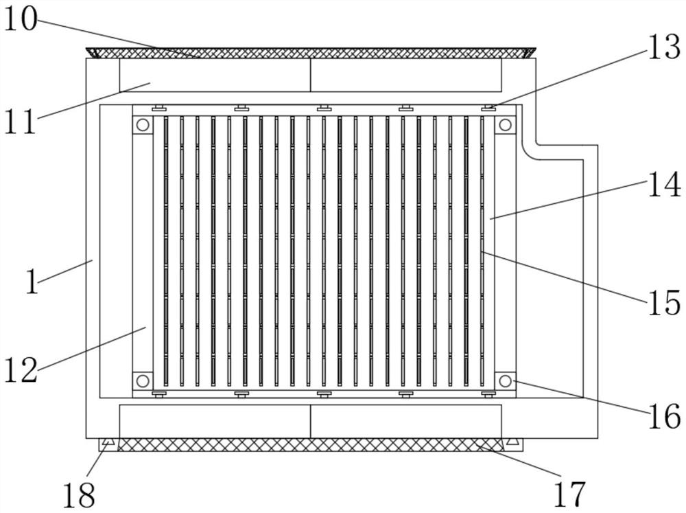
[0032] see Figure 2-9 Shown: a protection device for a mine belt conveyor controller, including a main box 1, a support frame 2 is provided below both sides of the bottom of the main box 1, and a lifting column 3 is installed above both ends of the support frame 2 , a posture adjustment mechanism is installed on the top of the lifting column 3, a spirit level is installed around the bottom of the main chassis 1, and suspension rings 7 are installed on the top of the posture adjustment mechanism. Evenly distributed shock absorbers 9, a shielding plate 10 is installed on the top of the main chassis 1, two cooling fans 11 are embedded in the top pl...


PUM


Abstract

The invention relates to a protection device for a mining belt conveyor controller, which comprises a mainframe box, support frames are arranged below two sides of the bottom of the mainframe box, lifting upright posts are mounted above two ends of each support frame, posture adjusting mechanisms are mounted at the tops of the lifting upright posts, gradienters are mounted around the bottom of the mainframe box, and the gradienters are mounted on the periphery of the bottom of the mainframe box. Hanging rings are mounted at the tops of the posture adjusting mechanisms, a shielding plate is mounted at the top of the mainframe box, two cooling fans are embedded in the middles of a top plate and a bottom plate of the mainframe box, and a plurality of supporting plates arranged side by side are mounted in the mainframe box and located between the cooling fans on the two sides; a heat dissipation plate for cooling and heat dissipation of the circuit board is installed on one side of the supporting plate, external low-temperature air is conducted into the mainframe box from the bottom of the mainframe box along with an air channel formed by the heat dissipation fans on the upper side and the lower side, so that heat is rapidly taken away, and rapid heat dissipation is conducted in heat conduction air flow output by the heat dissipation fans through the heat dissipation fins.

Description

technical field [0001] The invention relates to the technical field of controller protection, in particular to a protection device for a mine belt conveyor controller. Background technique [0002] The mine-used belt conveyor controller monitors the status of many operating parts of the entire equipment in real time, responds to potential failure factors in a timely manner, and enables the various components of the equipment to coordinate and operate normally. Its working environment is harsh, Complex and dangerous, so it is necessary to install a peripheral chassis to protect the mine belt conveyor controller. The existing protection devices for mine belt conveyor controllers are as follows: figure 1 shown. [0003] The patent document with the publication number CN113371418A discloses a mine belt conveyor controller protection device, including a protection box, which is slidably installed on the fixed top plate through a movable hanging buckle. Assemblies, fixed frames ...

Claims


Application Information

Patent Timeline
Patent Type & Authority Applications(China)
IPC IPC(8): B65G43/00B65G43/02H05K7/20
CPCB65G43/00B65G43/02H05K7/20136
Inventor 尹良贵李旺然蔡云龙向栋梁徐剑边江孔德全姚志远田建波贾瑞堂
Owner HUAINAN WANTAI ELECTRONICS
Learn More