Imaging method and system

An imaging method and imaging system technology, applied in the field of data processing, can solve problems such as slow imaging speed, and achieve the effect of fast imaging speed

Active Publication Date: 2021-06-22
PENG CHENG LAB
View PDF4 Cites 0 Cited by
  • Summary
  • Abstract
  • Description
  • Claims
  • Application Information

AI Technical Summary

Problems solved by technology

[0005] The main purpose of the present invention is to provide an imaging method and system, aiming to solve the problem of slow underwater three-dimensional imaging of orbital angular momentum in the prior art

Method used


Image

  • Imaging method and system
  • Imaging method and system
  • Imaging method and system

Examples


no. 1 example

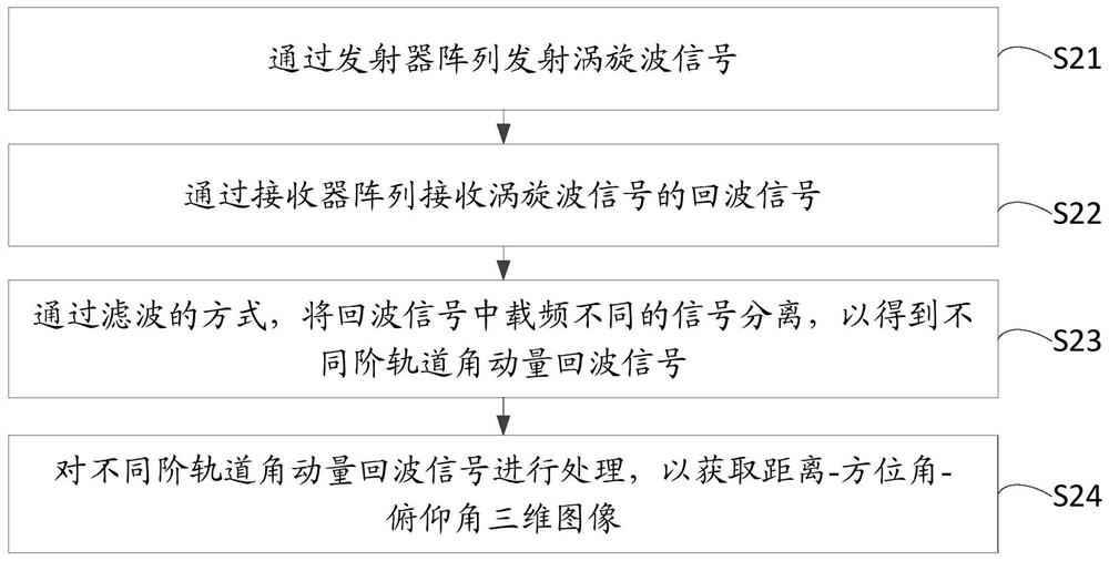
[0086] Based on the first embodiment, a second embodiment of the imaging method of the present invention is proposed. In the embodiment of the present invention, step S22 includes:

[0087] Step S221: Obtain the carrier frequency corresponding to each order of orbital angular momentum signal.

[0088] Wherein, the carrier frequency corresponding to each order of orbital angular momentum signal can be flexibly set according to actual needs.

[0089] Step S222: According to N, determine the initial phase of each order orbital angular momentum signal corresponding to each transmitter.

[0090] In the embodiment of the present invention, the initial phase of each order of orbital angular momentum signal corresponding to each transmitter is different, wherein, the orbital angle of each order corresponding to each transmitter can be determined according to N (that is, the number of transmitters in the transmitter array) The initial phase of the momentum signal.

[0091] In some e...


PUM


Abstract

The invention relates to the technical field of data processing, and discloses an imaging method and system. The imaging method comprises the following steps: transmitting a vortex wave signal through a transmitter array, wherein the vortex wave signal comprises an alpha-order orbital angular momentum signal, alpha is an integer greater than or equal to 2, and carrier frequencies of different orders of orbital angular momentum signals are different; receiving an echo signal of the vortex wave signal through a receiver array, wherein the echo signal comprises an alpha-order orbital angular momentum echo signal; separating signals with different carrier frequencies in the echo signals in a filtering mode so that orbital angular momentum echo signals with different orders are obtained; and processing different orders of orbital angular momentum echo signals to obtain a distance-azimuth angle-pitch angle three-dimensional image so that the problem of low imaging speed in the prior art is solved.

Description

technical field [0001] The invention relates to the field of data processing, in particular to an imaging method and system. Background technique [0002] Underwater 3D imaging can perform multi-view and high-resolution observation of underwater targets, and has urgent application requirements and broad application prospects in the fields of underwater vehicle obstacle avoidance, seabed topography mapping, and oil pipeline inspection. [0003] In the underwater three-dimensional imaging, the three-dimensional image is obtained by transmitting the vortex wave signal, receiving the echo signal, and processing the echo signal. [0004] However, with the existing three-dimensional imaging method of orbital angular momentum, the imaging speed is slow. Contents of the invention [0005] The main purpose of the present invention is to provide an imaging method and system, aiming to solve the problem of slow orbital angular momentum underwater three-dimensional imaging in the pri...

Claims


Application Information

Patent Timeline
Patent Type & Authority Applications(China)
IPC IPC(8): G01S13/89
CPCG01S13/89Y02A90/30
Inventor 孙晓雨李胜全罗明成张翼陈明
Owner PENG CHENG LAB
Why Eureka
Try Eureka