Optical identification system, optical identification method and electronic equipment

A technology of optical recognition and electronic equipment, applied in the fields of characters, automatic reading and recognition of two-dimensional codes, and barcodes, which can solve the problems that the optical recognition system cannot take into account the large field of view and high precision, and achieve rapid detection, efficient and accurate detection, and stable recognition Effect

Pending Publication Date: 2021-07-16
苏州协尔智能光电有限公司
View PDF0 Cites 1 Cited by
  • Summary
  • Abstract
  • Description
  • Claims
  • Application Information

AI Technical Summary

Problems solved by technology

[0003] In view of the above-mentioned shortcomings of the prior art, the purpose of the present invention is to provide an optical identification system, an optical identification method and electronic equipment, which are used to solve the technical problem that the optical identification system in the prior art cannot take into account both large field of view and high precision

Method used


Image

  • Optical identification system, optical identification method and electronic equipment
  • Optical identification system, optical identification method and electronic equipment
  • Optical identification system, optical identification method and electronic equipment

Examples


Embodiment Construction

[0038] Embodiments of the present invention are described below through specific examples, and those skilled in the art can easily understand other advantages and effects of the present invention from the content disclosed in this specification. The present invention can also be implemented or applied through other different specific implementation modes, and various modifications or changes can be made to the details in this specification based on different viewpoints and applications without departing from the spirit of the present invention.

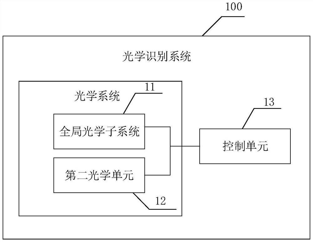
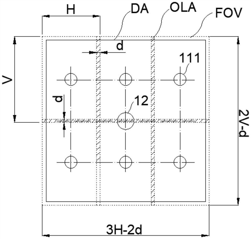
[0039] see Figure 1-4 . It should be noted that the diagrams provided in this embodiment are only schematically illustrating the basic idea of ​​the present invention, and only the components related to the present invention are shown in the diagrams rather than the number, shape and shape of the components in actual implementation. Dimensional drawing, the type, quantity and proportion of each component can be changed arbitrarily d...


PUM


Abstract

The invention provides an optical recognition system, an optical recognition method and electronic equipment, and the optical recognition system comprises: a global optical subsystem which is formed by combining a plurality of first optical units capable of recognizing a first recognition target according to a certain arrangement mode, wherein the combined visual field of the global optical subsystem covers a detection area provided with the first identification target; a second optical unit, wherein the visual field of the second optical unit covers the detection area; the control unit that is respectively connected with the global optical subsystem and the second optical unit, wherein the control unit is configured to position and identify the first identification target in the detection area by using image data acquired by the global optical subsystem and the second optical unit. According to the invention, detection can be carried out in a large-view range, and identification can be carried out on an identification target with a smaller scale in the large-view range.

Description

technical field [0001] The invention relates to the technical field of automatic reading and recognition of characters, barcodes and two-dimensional codes, in particular to an optical recognition system, an optical recognition method and electronic equipment. Background technique [0002] In the logistics industry, in order to speed up the delivery time, product classification is gradually replaced by an automatic identification system composed of optics and identification software. The automatic identification system can provide information for product labels (including characters, barcodes, and QR codes, etc.) , give proper classification and treatment. However, the existing automatic identification system has its limitations. If it is necessary to quickly identify items, a larger identification field of view is often required; in addition, the labels of products have various sizes and styles. Therefore, it is desirable to use a single optical system to achieve It is diff...

Claims


Application Information

Patent Timeline
IPC IPC(8): G06K7/10G06K9/32
CPCG06K7/10831G06K7/10722G06V10/25
Inventor 余承桓
Owner 苏州协尔智能光电有限公司
Why Eureka
Try Eureka