Laser marking device and process for tire production

A laser marking and tire technology, applied in auxiliary devices, laser welding equipment, manufacturing tools, etc., can solve the problems of poor use effect, prolonged tire positioning time, and inability to turn tires, etc., and achieve good use effect

Active Publication Date: 2021-11-30
山东新豪克轮胎有限公司
View PDF11 Cites 0 Cited by
  • Summary
  • Abstract
  • Description
  • Claims
  • Application Information

AI Technical Summary

Problems solved by technology

[0005] The purpose of the present invention is to provide a laser marking device and process for tire production to solve the problems in the above-mentioned background technology that the tire cannot be turned over, the use effect is poor, the positioning steps are complicated, and the tire positioning time is prolonged.

Method used


Image

  • Laser marking device and process for tire production
  • Laser marking device and process for tire production
  • Laser marking device and process for tire production

Examples


Embodiment 1

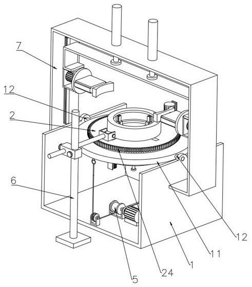
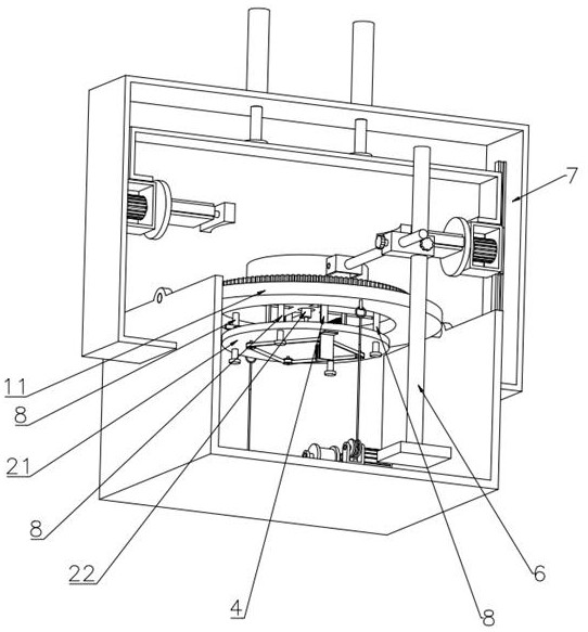
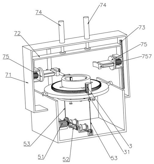
[0039] Such as Figure 1-Figure 12 As shown, a laser marking device for tire production provided by the present invention includes a U-shaped frame 1, an overturning ring 11 and two rotating shafts 12, and also includes a fixed plate 2, a lifting plate 21, an electric push rod 22, and a connecting plate 23 , circular rack 24, rotating motor 3, rotating gear 31, positioning assembly 4, overturning assembly 5, marking assembly 6, overturning assembly 7 and four sliding columns 8, two rotating shafts 12 are installed on U-shaped frame 1 for rotation The top of the flip ring 11 is fixedly connected to the two rotating shafts 12 on both sides, the top of the flip ring 11 is provided with an annular chute 111, the fixed disk 2 is arranged on the top of the flip ring 11, and the fixed disk 2 and the annular chute 111 Sliding fit, the four sliding columns 8 are rectangularly distributed on the bottom of the fixed plate 2, and the bottom ends of the four sliding columns 8 extend to the...

Embodiment 2

[0047] The process of a laser marking device for tire production provided by the present invention comprises the following steps,

[0048] Step S1, place the tire on the top of the fixed plate 2, and the positioning assembly 4 performs collision positioning on the inner wall of the tire, the rotating motor 3 drives the rotating gear 31 to rotate, the rotating gear 31 drives the circular rack 24 to rotate, and the circular rack 24 drives The fixed disk 2 rotates on the annular chute 111, the fixed disk 2 drives the tire to rotate, and the marking assembly 6 engraves patterns on the outer peripheral surface of the rotating tire;

[0049] Step S2, the overturning motor 51 drives the sprocket 540 in one of the overturning parts 53 to rotate, the sprocket 540 drives the winding shaft 532 to rotate, the winding shaft 532 drives the winding roller 533 to rotate, the winding roller 533 drives the steel rope 539 to wind and rewind, and the steel rope 539 utilizes the pulley 535 to pull...


PUM


Abstract

The invention relates to the technical field of laser processing, in particular to a laser marking device and process for tire production, which includes a U-shaped frame, an overturning ring and two rotating shafts, and also includes a fixed plate, a lifting plate, an electric push rod, a connecting plate, a round gear rack, rotating motor, rotating gear, positioning assembly, flipping assembly, marking assembly, flipping assembly and four sliding posts, the two sides of the flipping ring are respectively fixedly connected with the two rotating shafts, and the fixed disk is set on the top of the flipping ring , the circular rack is set on the outer wall of the fixed plate, the rotating motor is vertically arranged on the top of the fixed plate, the rotating gear is fixedly connected with the output shaft of the rotating motor, the positioning assembly is installed on the lifting plate, and the turning assembly is arranged on the U At the bottom of the type frame, the marking assembly is arranged on the side of the U-shaped frame, and the turning assembly is installed on the outer wall of the U-shaped frame. The invention realizes the parameters such as brand, size and speed level engraved on the side of the tire, and the use effect Well, the positioning steps are simple, reducing the tire positioning time.

Description

technical field [0001] The invention relates to the technical field of laser processing, in particular to a laser marking device and process for tire production. Background technique [0002] Tires are circular elastic rubber products that are rolled on the ground and rolled on various vehicles or machinery. Usually installed on metal rims, it can support the body, buffer external impact, realize contact with the road surface and ensure the driving performance of the vehicle. Tires are often used under complex and harsh conditions, and they are subjected to various deformations, loads, forces, and high and low temperature effects during driving, so they must have high load-bearing performance, traction performance, and cushioning performance. At the same time, it is also required to have high wear resistance and flex resistance, as well as low rolling resistance and heat generation. [0003] The Chinese invention patent with the publication number CN106863768B discloses a ...

Claims


Application Information

Patent Timeline
Patent Type & Authority Patents(China)
IPC IPC(8): B23K26/362B23K26/70B23K26/08B23K37/053
CPCB23K26/362B23K26/702B23K37/053B23K26/0869B23K2101/007B23K2101/006
Inventor 朱黎峰施晓路刘伟彬许美华于慧王少朋
Owner 山东新豪克轮胎有限公司
Why Eureka
Try Eureka