
Bluetooth headset quick battery replacement structure and battery replacement method thereof
A technology for Bluetooth headsets and earphones, applied in the directions of earpieces/headphone accessories, rechargeable batteries/devices, etc., can solve the problems that the earphones cannot be used, affect the experience of using the earphones, etc., and achieve the effect of convenient operation.
- Summary
- Abstract
- Description
- Claims
- Application Information
AI Technical Summary
Problems solved by technology
Method used
Image

Examples
Embodiment 1
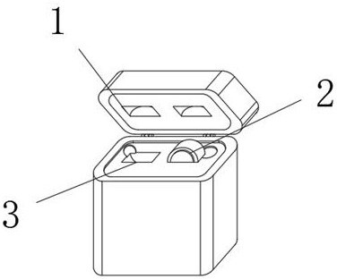
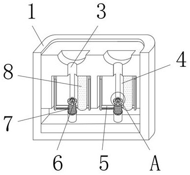
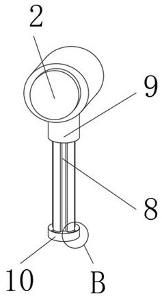
[0039] Embodiment one: if Figure 1-2 As shown, a bluetooth earphone fast battery replacement structure includes an earphone 2 and an earphone compartment 1 for charging the earphone 2. The earphone compartment 1 is provided with an earphone slot 3 that fits the earphone 2 inside. The earphone 2 is assembled with a replaceable Battery cell 8, inside the earphone compartment 1 is also equipped with a battery exchange slot 4, the battery exchange slot 4 is connected to the earphone slot 3, and the interior of the battery exchange slot 4 is provided with a replacement battery cell 8 in the earphone 2 The power exchange device 7 is connected with a drive plate 6 in the middle of the power exchange device 7 , and the drive plate 6 is slidably connected to the inside of the earphone slot 3 .
[0040] When in use, when the internal power of the earphone is used up, insert the earphone 2 into the earphone slot 3, the earphone 2 presses the drive plate 6, so that the battery changing d...
Embodiment 2
[0041] Embodiment two: if Figure 1-5 As shown, on the basis of Embodiment 1, an elastic slider 11 is fixedly connected to the side end surface of the drive plate 6, and a chute matching the elastic slider 11 is opened inside the earphone slot 3, and the chute is filled with springs. One end of the spring is fixedly connected with the bottom of the chute, and the other end of the spring is fixedly connected with the elastic slider 11.
[0042] During use, the drive plate 6 is slidably connected to the inside of the earphone groove 3 through the elastic slider 11, and the elastic slider 11 is elastically connected to the matching groove on the inner wall of the earphone groove 3 by being connected with a spring. The block 11 and the spring are elastically connected to the inside of the earphone slot 3 .
[0043] like Figure 1-5 As shown in and 9, the lower end surface of the drive plate 6 is fixedly connected with an externally threaded pipe 15, and the power exchange device...
PUM
 Abstract
Description
Claims
Application Information