Double-synchronous-swing parallelogram-driven roller shutter type flapping-wing unmanned aerial vehicle

A parallelogram and double-synchronization technology, which is applied in the direction of unmanned aircraft, helicopters, aircraft, etc., can solve the problems that restrict the popularization and application of flapping-wing aircraft, the overall efficiency of flapping-wing aircraft is low, and the aerodynamic efficiency is low, so as to achieve simple structure , low reset resistance and low production cost

Pending Publication Date: 2022-01-11
GLOBAL INST OF SOFTWARE TECH
View PDF0 Cites 0 Cited by
  • Summary
  • Abstract
  • Description
  • Claims
  • Application Information

AI Technical Summary

Problems solved by technology

The main reason for the overall low efficiency of flapping wing aircraft is that most of the current research simply imitates the shape and flapping motion of the wings of birds or insects, but it is difficult to realize the use of the wing's own posture and structure in the process of flapping wings of flying creatures. The change of air resistance reduces air resistance and generates unsteady aerodynamic force, and the resulting low aerodynamic efficiency seriously restricts the popularization and application of flapping-wing aircraft

Method used


Image

  • Double-synchronous-swing parallelogram-driven roller shutter type flapping-wing unmanned aerial vehicle
  • Double-synchronous-swing parallelogram-driven roller shutter type flapping-wing unmanned aerial vehicle
  • Double-synchronous-swing parallelogram-driven roller shutter type flapping-wing unmanned aerial vehicle

Examples


Embodiment 1

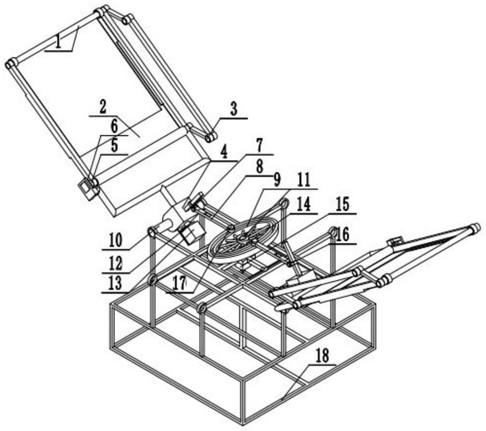
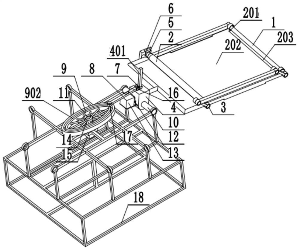
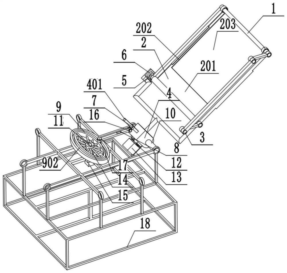
[0036] Example 1: Combining figure 1 , figure 2 , image 3 , Figure 4 , Figure 5 , Figure 6 , Figure 7 , Figure 8 , Figure 9 , Figure 10 and Figure 11 , a high-voltage wire inspection drone that uses a double-synchronous swing parallelogram transmission rolling shutter flapping wing drone. Including flapping wing, connecting piece 4, first reducer 5, drive motor 6, transmission mechanism, swing shaft 10, second reducer 12, stepping motor 13, third reducer 14, drive motor 15 and fuselage frame 18 , the fuselage frame 18 is symmetrically installed and fixed with two horizontal swing shafts 10, the two connecting parts 4 are respectively connected to the two swing shafts 10 and rotate relative to each other, and the two flapping wings are respectively connected to the two connecting parts 4 and can be relatively rotated, the flapping wing includes a flapping wing frame 1, and a roller blind 2 installed on the flapping wing frame 1, a parallelogram mechanism and...

Embodiment 2

[0037] Example 2: Combining figure 1 , figure 2 , image 3 , Figure 4 , Figure 5 , Figure 6 , Figure 7 , Figure 8 , Figure 9 , Figure 10 and Figure 11 , a high-level fire-fighting drone that adopts a double-synchronous swing parallelogram transmission rolling shutter flapping wing drone. Including flapping wing, connecting piece 4, first reducer 5, drive motor 6, transmission mechanism, swing shaft 10, second reducer 12, stepping motor 13, third reducer 14, drive motor 15 and fuselage frame 18 , the fuselage frame 18 is symmetrically installed and fixed with two horizontal swing shafts 10, the two connecting parts 4 are respectively connected to the two swing shafts 10 and rotate relative to each other, and the two flapping wings are respectively connected to the two connecting parts 4 and can be relatively rotated, the flapping wing includes a flapping wing frame 1, and a roller blind 2 installed on the flapping wing frame 1, a parallelogram mechanism and a...


PUM


Abstract

The invention relates to a double-synchronous-swing parallelogram-driven roller shutter type flapping-wing unmanned aerial vehicle. The unmanned aerial vehicle comprises flapping wings, swing shafts, connecting pieces, first speed reducers, driving motors, a transmission mechanism, second speed reducers, stepping motors, a fuselage frame, third speed reducers and a motor; the two swing shafts in the horizontal direction are symmetrically and fixedly mounted on the two sides of the fuselage frame, and the two connecting pieces are connected to the two swing shafts correspondingly and rotate relatively; the two flapping wings are connected to the two connecting pieces respectively and can rotate relatively, each flapping wing comprises a flapping wing frame and a roller blind mounted on the flapping wing frame, and a parallelogram mechanism and a driving motor are further arranged in each flapping wing frame and used for switching between the working state and the reset state of the flapping wings; the transmission mechanism is connected to the two connecting pieces; and the motor drives the transmission mechanism to move after being decelerated by the third speed reducer, so that the two connecting pieces synchronously swing up and down, and the two stepping motors respectively drive the two flapping wings to rotate after being decelerated by the two second speed reducers.

Description

technical field [0001] The invention relates to the field of movable-wing aircraft and flying robots, in particular to a double-synchronous swing parallelogram transmission rolling shutter flapping-wing unmanned aerial vehicle for unmanned aerial vehicles. Background technique [0002] There are three flight types of aircraft flying: fixed wing, rotary wing and flapping wing. Among them, flapping wing flight is the flying mode adopted by flying creatures in nature. It mainly uses the up and down flapping of the wings to generate lift and thrust at the same time. , hovering and propulsion functions are based on one body, and at the same time have strong maneuverability and flexibility, and are more suitable for flying around obstacles. For small-sized and low-speed aircraft flying under low Reynolds numbers, the unsteady lift generated by the flapping wing is much greater than the constant lift of the fixed wing; from the perspective of thrust, the propulsion efficiency of th...

Claims


Application Information

Patent Timeline
Patent Type & Authority Applications(China)
IPC IPC(8): B64C33/00B64C33/02B64C21/02
CPCB64C33/00B64C33/02B64C21/02B64U2101/00
Inventor 邱明陈永平赵雪王杰夏青元王涛胡诚廖振强
Owner GLOBAL INST OF SOFTWARE TECH
Why Eureka
Try Eureka