A hierarchical core-pulling method for injection molds

An injection mold and mold technology, applied in the field of grading core pulling of injection molds, can solve problems such as large resistance, easy failure of core pulling action, and reduce reset resistance, and achieve the effects of ensuring reliability, avoiding action failure, and reducing reset resistance.

Active Publication Date: 2019-01-25
SHENTONG TECH GRP CO LTD
View PDF5 Cites 0 Cited by
  • Summary
  • Abstract
  • Description
  • Claims
  • Application Information

AI Technical Summary

Problems solved by technology

[0005] The purpose of the present invention is to solve the problem that the core-pulling action of the existing injection mold graded core-pulling structure is prone to failure, the resistance when resetting is large, and the longitudinal core-pulling in the graded core-pulling cannot be satisfied with the mold parting direction. In order to solve the problem of angle requirements, we provide a graded core-pulling method for injection molds, which can not only significantly improve the stability and reliability of graded core-pulling, greatly reduce the reset resistance, but also meet the requirements of graded core-pulling with inclined longitudinal core-pulling. Core requirements

Method used


Image

  • A hierarchical core-pulling method for injection molds
  • A hierarchical core-pulling method for injection molds
  • A hierarchical core-pulling method for injection molds

Examples


Embodiment 1

[0036] Embodiment 1: a kind of graded core-pulling method of injection mold, comprises the following steps:

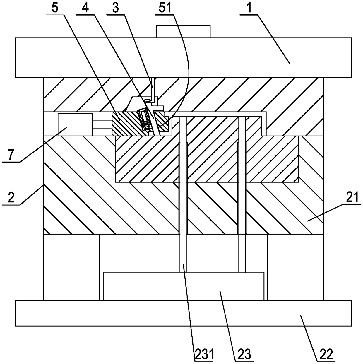
[0037] a. When the mold cavity in the mold closing state is filled with molten plastic and cooled and shaped, the movable mold retreats and separates from the fixed mold, and the lower end of a vertical core-pulling rod 3 fixed on the fixed mold is hooked The tail end of the core-pulling core allows the core-pulling core to move axially backward from the forming position obliquely in the inclined guide hole 51 of the core-pulling slider. The core-pulling slider is used to shape the lateral shape of the product. The core-pulling core is used for the inclined hole groove in the lateral shape of the molded product, and the core-pulling direction of the core-pulling slider and the core-pulling core is inconsistent. When the forming end of the front end of the core-pulling core withdraws from the inclined hole groove of the product and retracts into the guide hole, the firs...

Embodiment 2

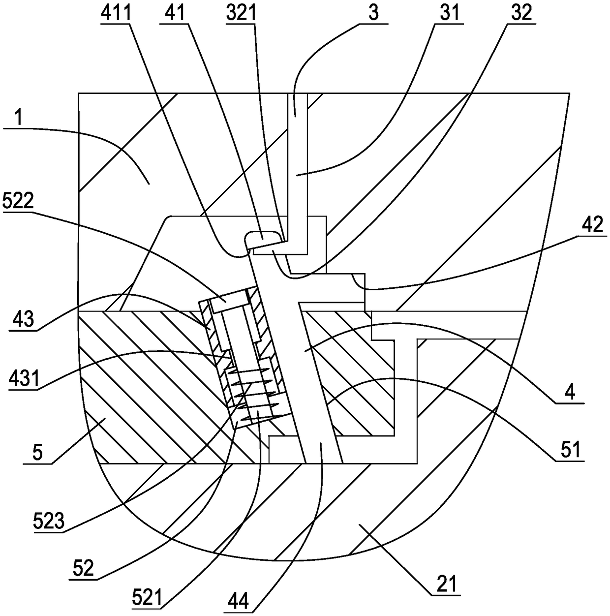
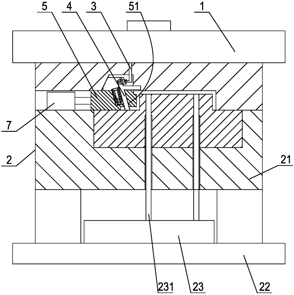
[0045] Embodiment 2: as image 3 , Figure 4 Shown, a kind of graded core-pulling method of injection mold comprises the following steps:

[0046]a. When the mold cavity in the mold closing state is filled with molten plastic and cooled and shaped, the movable mold 2 moves back and separates from the fixed mold 1, and the lower end of a vertical core-pulling rod 3 fixedly arranged on the fixed mold Hook the tail end of the core-pulling core 4 to move the core-pulling core obliquely and axially backward from the molding position in the inclined guide hole 51 of the core-pulling slider 5 . When the forming end of the front end of the core-pulling core withdraws from the inclined hole groove of the product and retracts into the guide hole, the first-level core-pulling of the product is completed. At this time, the tail end of the core-pulling core that moves obliquely forms a longitudinal displacement on the one hand. , producing a lateral displacement. The core pulling rod in...


PUM


Abstract

The invention discloses a graded core pulling method for an injection mold. During mold separation, a core pulling oil cylinder drives a first-grade core pulling slide block slidably connected into a second-grade core pulling slide block to slide backwards, and the first-grade core pulling slide block drives a core pulling mold core slidably connected with the first-grade core pulling slide block to axially recede so as to complete first-grade core pulling; the core pulling oil cylinder continues to act, and therefore the first-grade core pulling slide block pulls the second-grade core pulling slide block to recede so as to complete second-grade core pulling; then a product is ejected from a moving mold body; the core pulling oil cylinder backwards acts to enable the first-grade core pulling slide block to forwards slide so as to drive the core pulling mold core to axially move forwards and to stretch out of the forming end of the second-grade core pulling slide block; and the core pulling oil cylinder continues to act so as to drive the second-grade core pulling slide block and the core pulling mold core to synchronously move forwards and to reset, and at this time, injection molding of the next product can be started. By adoption of the graded core pulling method, the structure of the mold can be simplified to adapt to lateral core pulling, in the two random directions, of the same lateral shape of the product, and receding of the core pulling mold core and the slide blocks can be avoided.

Description

technical field [0001] The invention relates to the technical field of injection molds, in particular to a hierarchical core-pulling method for injection molds. Background technique [0002] Plastic products are very common in production and daily life, among which injection molding is the most common plastic product molding method, which usually includes a fixed mold on the upper side of the parting surface, a movable mold on the lower side of the parting surface, and a top plate, etc. , wherein the fixed mold is provided with a sprue sleeve, and the fixed mold and the movable mold are respectively provided with molding parts corresponding to the upper surface and the lower surface of the product. In order to make the molded product stay on the side of the movable mold, usually the molding part on the fixed mold is a cavity corresponding to the shape of the product, while the molding part on the movable mold is a core corresponding to the inner cavity of the product. The m...

Claims


Application Information

Patent Timeline
Patent Type & Authority Patents(China)
IPC IPC(8): B29C45/33B29C45/40
CPCB29C45/332B29C45/4005
Inventor 方立锋蔡炳芳项勇毛元源
Owner SHENTONG TECH GRP CO LTD
Why Eureka
Try Eureka