Driving energy-adjustable continuous winged device with variable windward area and variable dip angle

A technology of windward area and variable inclination angle, which is applied in the direction of motor vehicles, transportation and packaging, and affects the air flow flowing through the surface of the aircraft, which can solve the problems that cannot realize vertical take-off and landing and hovering in the air, restricting the popularization and application of flapping-wing aircraft, The overall low efficiency of the flapping wing aircraft has achieved the effect of simple structure, small reset resistance and simple installation

Pending Publication Date: 2022-01-11
江苏第二师范学院
View PDF10 Cites 0 Cited by
  • Summary
  • Abstract
  • Description
  • Claims
  • Application Information

AI Technical Summary

Problems solved by technology

The main reason for the overall low efficiency of flapping wing aircraft is that most of the current research simply imitates the shape and flapping motion of the wings of birds or insects, but it is difficult to realize the use of the wing's own posture and structure in the process of flapping wings of flying creatures. The change of air resistance reduces air resistance and generates unsteady aerodynamic force, and the resulting low aerodynamic efficiency seriously restricts the popularization and application of flapping-wing aircraft
At the same time, most of the current flapping-wing aircraft cannot achieve vertical take-off and landing and hovering in the air, and their flexibility and maneuverability are not good enough

Method used


Image

  • Driving energy-adjustable continuous winged device with variable windward area and variable dip angle
  • Driving energy-adjustable continuous winged device with variable windward area and variable dip angle
  • Driving energy-adjustable continuous winged device with variable windward area and variable dip angle

Examples


Embodiment 1

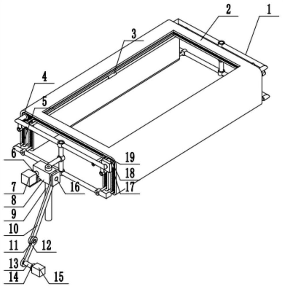
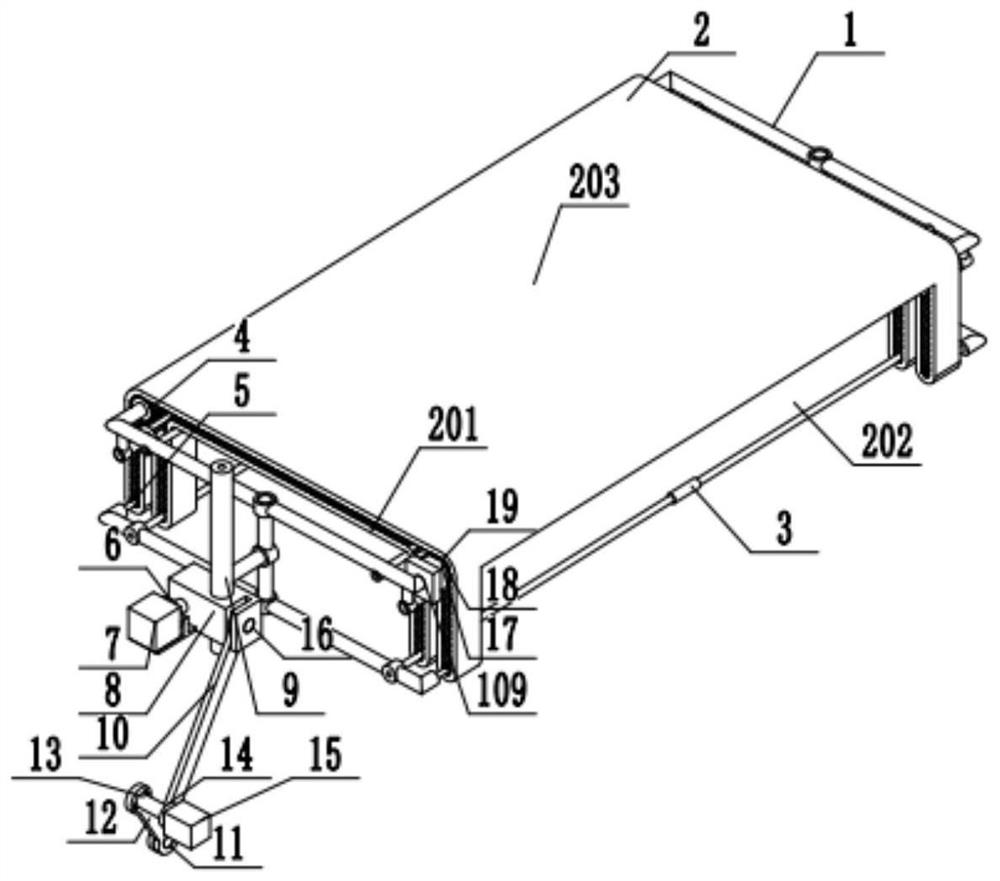
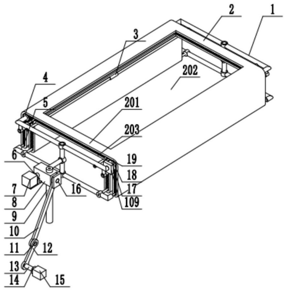
[0033] Example 1: Combining figure 1 , figure 2 , image 3 , Figure 4 , Figure 5 , Figure 6 , Figure 7 , Figure 8 , Figure 9 and Figure 10 , using a variable windward area and variable inclination angle to drive an energy-adjustable continuous winged device for high-voltage wire inspection drones. Including belt wing, connecting piece 8, transmission mechanism and slideway 9, belt wing is connected on the connecting piece 8 and can rotate relatively, connecting piece 8 is slidably connected on the slideway 9, and slideway 9 is arranged on the aircraft, and belt wing comprises Winged frame 1, and the continuous soft belt 2 sleeved on the winged frame 1, the large winged pulley 4, the small winged pulley 5, the tension pulley 3 and the driving motor are also arranged in the winged frame 1 17. It is used to control the movement of the soft belt 2 around the winged frame 1, and the transmission mechanism is connected to the connector 8; on the winged frame 1, ther...

Embodiment 2

[0034] Example 2: Combining figure 1 , figure 2 , image 3 , Figure 4 , Figure 5 , Figure 6 , Figure 7 , Figure 8 , Figure 9 and Figure 10 , a special UAV for high-rise building fire-fighting that uses variable windward area and variable inclination to drive energy-adjustable continuous winged devices. Including belt wing, connecting piece 8, transmission mechanism and slideway 9, belt wing is connected on the connecting piece 8 and can rotate relatively, connecting piece 8 is slidably connected on the slideway 9, and slideway 9 is arranged on the aircraft, and belt wing comprises Winged frame 1, and the continuous soft belt 2 sleeved on the winged frame 1, the large winged pulley 4, the small winged pulley 5, the tension pulley 3 and the driving motor are also arranged in the winged frame 1 17. It is used to control the movement of the soft belt 2 around the winged frame 1, and the transmission mechanism is connected to the connector 8; on the winged frame 1,...


PUM


Abstract

The invention discloses a driving energy-adjustable continuous winged device with variable windward area and variable dip angle, wherein the device comprises a belt wing, a slide way and a connecting piece; the belt wing is connected to the connecting piece and can rotate relatively, the connecting piece is connected to the slide way in a sliding mode, the slide way is arranged on an aircraft, and the belt wing comprises a belt wing frame and a soft belt mounted on the belt wing frame; and large belt wheels, small belt wheels, tensioning wheels and driving motors are further arranged in the winged frame and used for switching between the working state and the reset state of the belt wing. Compared with the prior art, the invention has the characteristics of small reset stroke resistance, large and stable working stroke thrust, high aerodynamic efficiency, capability of simultaneously adjusting lift force and thrust, simpler device structure and convenience in manufacturing, and can be widely applied to various small aircrafts and unmanned aerial vehicles with low Reynolds number flight.

Description

technical field [0001] The invention relates to the field of movable wing aircraft and flying robots, in particular to a continuous winged device with variable windward area and variable inclination angle driving energy adjustable for unmanned aerial vehicles. Background technique [0002] There are three flight types of aircraft flying: fixed wing, rotary wing and flapping wing. Among them, flapping wing flight is the flying mode adopted by flying creatures in nature. It mainly uses the up and down flapping of the wings to generate lift and thrust at the same time. , hovering and propulsion functions are based on one body, and at the same time have strong maneuverability and flexibility, and are more suitable for flying around obstacles. For small-sized and low-speed aircraft flying under low Reynolds numbers, the unsteady lift generated by the flapping wing is much greater than the constant lift of the fixed wing; from the perspective of thrust, the propulsion efficiency o...

Claims


Application Information

Patent Timeline
Patent Type & Authority Applications(China)
IPC IPC(8): B64C33/02B64C21/08
CPCB64C33/02B64C21/08B64U2101/00
Inventor 薛岩
Owner 江苏第二师范学院
Why Eureka
Try Eureka