Synchronous swing type variable-dip-angle driving energy-adjustable four-continuous-wing aircraft

A technology of synchronous swing and variable inclination, which is applied in the direction of aircraft, unmanned aircraft, motor vehicles, etc., can solve the problems that restrict the popularization and application of flapping wing aircraft, the overall efficiency of flapping wing aircraft is low, and the aerodynamic efficiency is low. Simple, low reset resistance, and improved aerodynamic efficiency

Pending Publication Date: 2022-01-11
GLOBAL INST OF SOFTWARE TECH
View PDF0 Cites 0 Cited by
  • Summary
  • Abstract
  • Description
  • Claims
  • Application Information

AI Technical Summary

Problems solved by technology

The main reason for the overall low efficiency of flapping wing aircraft is that most of the current research simply imitates the shape and flapping motion of the wings of birds or insects, but it is difficult to realize the use of the wing's own posture and structure in

Method used


Image

  • Synchronous swing type variable-dip-angle driving energy-adjustable four-continuous-wing aircraft
  • Synchronous swing type variable-dip-angle driving energy-adjustable four-continuous-wing aircraft
  • Synchronous swing type variable-dip-angle driving energy-adjustable four-continuous-wing aircraft

Examples


Embodiment 1

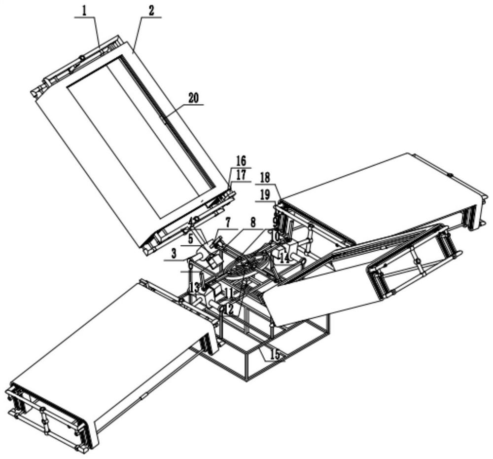
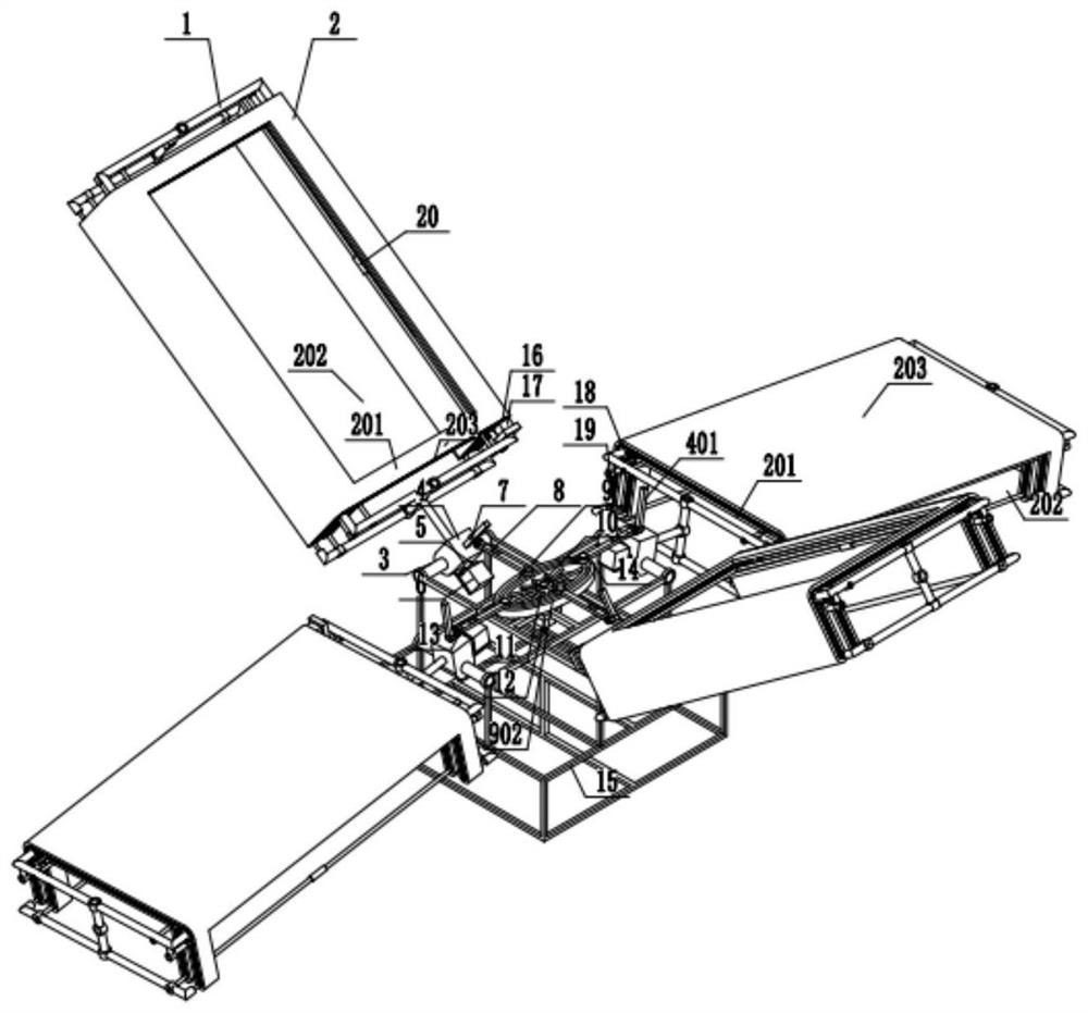
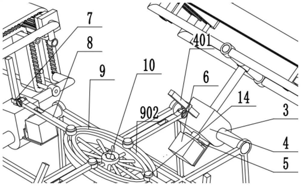
[0036] Example 1: Combining figure 1 , figure 2 , image 3 , Figure 4 , Figure 5 , Figure 6 , Figure 7 , Figure 8 , Figure 9 , Figure 10 and Figure 11 , a high-voltage wire inspection UAV that uses a synchronous swing variable-inclination drive energy-adjustable four continuous winged aircraft. Including belt wings, swing shaft 3, connecting piece 4, first reducer 5, stepper motor 6, transmission mechanism, second reducer 11, motor 12, fuselage frame 15, third reducer 16 and drive motor 17, The fuselage frame 15 is symmetrically installed and fixed with four horizontal swing shafts 3, the four connecting parts 4 are respectively connected to the four swing shafts 3 and rotate relative to each other, and the four belt wings are connected to the four connecting parts 4 respectively. And can be relatively rotated, the wing includes a wing frame 1, and a continuous soft belt 2 sleeved on the wing frame 1, a third speed reducer 16 and a drive motor 17 are arrange...

Embodiment 2

[0037] Example 2: Combining figure 1 , figure 2 , image 3 , Figure 4 , Figure 5 , Figure 6 , Figure 7 , Figure 8 , Figure 9 , Figure 10 and Figure 11 , a high-rise building fire-fighting special UAV that uses a synchronous swing variable-inclination drive energy-adjustable four continuous winged aircraft. Including belt wings, swing shaft 3, connecting piece 4, first reducer 5, stepper motor 6, transmission mechanism, second reducer 11, motor 12, fuselage frame 15, third reducer 16 and drive motor 17, The fuselage frame 15 is symmetrically installed and fixed with four horizontal swing shafts 3, the four connecting parts 4 are respectively connected to the four swing shafts 3 and rotate relative to each other, and the four belt wings are connected to the four connecting parts 4 respectively. And can be relatively rotated, the wing includes a wing frame 1, and a continuous soft belt 2 sleeved on the wing frame 1, a third speed reducer 16 and a drive motor 17...


PUM


Abstract

The invention relates to a synchronous swing type variable-dip-angle driving energy-adjustable four-continuous-wing aircraft. The aircraft comprises belt wings, swing shafts, connecting pieces, first speed reducers, stepping motors, a transmission mechanism, a second speed reducer, a motor, a fuselage frame, a third speed reducer and driving motors; the four swing shafts in the horizontal direction are symmetrically and fixedly mounted on the periphery of the fuselage frame, and the four connecting pieces are connected to the four swing shafts correspondingly and rotate relatively; the four belt wings are connected to the four connecting pieces respectively and can rotate relatively; each belt wing comprises a belt wing frame and a soft belt mounted on the belt wing frame; belt wheels, tensioning wheels and driving motors are further arranged in each belt wing frame and used for switching between the working state and the reset state of the belt wings; the transmission mechanism is connected to the two connecting pieces; the motor drives the transmission mechanism to move after being decelerated by the second speed reducer, so that the four connecting pieces synchronously swing up and down, and the four stepping motors respectively drive the four belt wings to rotate after being decelerated by the two first speed reducers.

Description

technical field [0001] The invention relates to the field of movable-wing aircraft and flying robots, in particular to a synchronous swing-type variable-inclination drive energy-adjustable quadruple continuous winged aircraft. Background technique [0002] There are three flight types of aircraft flying: fixed wing, rotary wing and flapping wing. Among them, flapping wing flight is the flying mode adopted by flying creatures in nature. It mainly uses the up and down flapping of the wings to generate lift and thrust at the same time. , hovering and propulsion functions are based on one body, and at the same time have strong maneuverability and flexibility, and are more suitable for flying around obstacles. For small-sized and low-speed aircraft flying under low Reynolds numbers, the unsteady lift generated by the flapping wing is much greater than the constant lift of the fixed wing; from the perspective of thrust, the propulsion efficiency of the flapping wing is higher than...

Claims


Application Information

Patent Timeline
IPC IPC(8): B64C33/00B64C33/02B64C21/08B64C1/00
CPCB64C33/00B64C33/02B64C21/08B64C1/00B64U2101/00
Inventor 邱明蔡伟义陈旭初顾诚华洪良廖振强
Owner GLOBAL INST OF SOFTWARE TECH
Why Eureka
Try Eureka