Wide-angle lens and imaging equipment

A technology of wide-angle lens and imaging surface, which is applied in the field of imaging lens, can solve the problems of thermal expansion and contraction of plastic lenses that are difficult to overcome, unfavorable lens miniaturization and light weight, and difficult manufacturing process of glass aspheric surface, so as to improve product competitiveness, Improve resolution and reduce distortion

Active Publication Date: 2022-05-10
JIANGXI LIANCHUANG ELECTRONICS CO LTD
View PDF7 Cites 0 Cited by
  • Summary
  • Abstract
  • Description
  • Claims
  • Application Information

AI Technical Summary

Problems solved by technology

In some occasions, imaging lenses are required to have good thermal stability and wide-angle characteristics, and all glass materials with relatively stable thermal expansion coefficients are used, resulting in high manufacturing costs and poor market competitiveness; at the same time, the existing wide-angle characteristics generally require an increase in the number of lenses. It is not conducive to miniaturization, but also increases aberrations and leads to poor image quality
[0003] At present, plastic lenses are mostly used to reduce costs and reduce weight. However, the thermal expansion and contraction characteristics of plastic lenses are difficult to overcome.
Of course, glass aspheric lenses can also be used to improve imaging quality and meet temperature performance requirements. However, glass aspheric lenses are difficult to manufacture, cost is high, and the lens volume is often large, which is not conducive to the miniaturization and light weight of the lens.

Method used


Image

  • Wide-angle lens and imaging equipment
  • Wide-angle lens and imaging equipment
  • Wide-angle lens and imaging equipment

Examples


no. 1 example

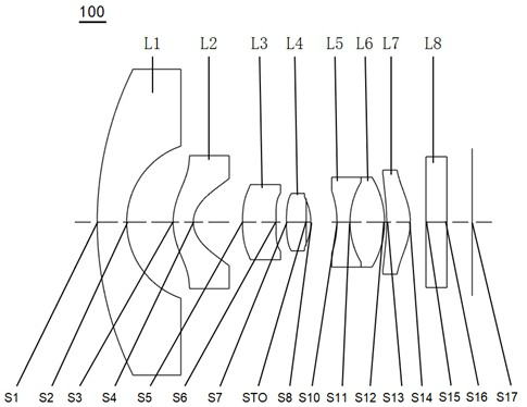
[0069] see figure 1 , which is a schematic structural view of the wide-angle lens 100 provided in the first embodiment of the present invention, the wide-angle lens 100 includes in sequence from the object side to the imaging surface along the optical axis: a first lens L1, a second lens L2, a third lens L3, a Four lenses L4, a diaphragm STO, a fifth lens L5, a sixth lens L6, a seventh lens L7, and a filter L8.

[0070] Wherein, the first lens L1 has negative refractive power, the object side S1 of the first lens is a convex surface, and the image side S2 of the first lens is a concave surface;

[0071] The second lens L2 has a negative refractive power, the object side S3 of the second lens is a convex surface, and the image side S4 of the second lens is a concave surface;

[0072] The third lens L3 has positive refractive power, the object side S5 of the third lens is a convex surface, and the image side S6 of the third lens is a convex surface at the near optical axis;

...

no. 2 example

[0087] see Figure 5 , is a schematic structural view of the wide-angle lens 200 provided by the second embodiment of the present invention. The structure of the wide-angle lens 200 provided by the second embodiment of the present invention is substantially the same as that of the wide-angle lens 100 provided by the first embodiment. The radius of curvature is chosen differently.

[0088] Please refer to Table 4, Table 5, and Table 6, which show the relevant parameters of the wide-angle lens 200 provided by the second embodiment of the present invention

[0089] Table 4

[0090]

[0091] table 5

[0092]

[0093] Table 6

[0094]

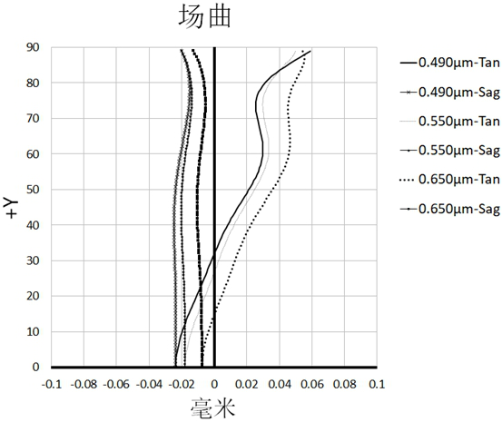
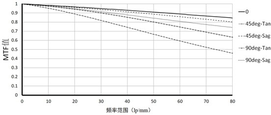
[0095] Please refer to Figure 6 , Figure 7 and Figure 8 , respectively show the field curvature curve, MTF diagram, and axial chromatic aberration curve diagram of the wide-angle lens 200 in the second embodiment. From Figure 6 It can be seen from the figure that the field curvature of the meridional image plane and the sagittal...

no. 3 example

[0097] see Figure 9 , which is a schematic diagram of the structure of the wide-angle lens 300 provided by the third embodiment of the present invention. The structure of the wide-angle lens 300 provided by the third embodiment of the present invention is substantially the same as that of the wide-angle lens 100 provided by the first embodiment. The radius of curvature is chosen differently.

[0098] Please refer to Table 7, Table 8, and Table 9, which show the relevant parameters of the wide-angle lens 300 provided by the third embodiment of the present invention:

[0099] Table 7

[0100]

[0101] Table 8

[0102]

[0103] Table 9

[0104]

[0105] Please refer to Figure 10 , Figure 11 and Figure 12 , respectively show the field curvature curve, MTF curve, and axial chromatic aberration curve of the wide-angle lens 300 in the third embodiment. From Figure 10 It can be seen from the figure that the field curvature of the meridional image plane and the sa...


PUM


Abstract

The invention discloses a wide-angle lens and imaging equipment. The wide-angle lens sequentially includes: a first lens with negative optical power from the object side to the imaging surface along the optical axis, the object side is convex, and the image side is concave; The second lens with positive refractive power has a convex surface on the object side and the concave surface on the image side; the third lens with positive refractive power has a convex surface on the object side; the fourth lens with positive refractive power has convex surfaces on both the object side and the image side ; Diaphragm; the fifth lens with negative power, its object side and image side are concave; the sixth lens with positive power, its object side and image side are convex, and the fifth lens and the sixth The lenses form a cemented body; the seventh lens with positive refractive power has a concave surface on the object side and a convex surface on the image side. The wide-angle lens has the advantages of miniaturization, super large viewing angle and high resolution.

Description

technical field [0001] The invention relates to the technical field of imaging lenses, in particular to a wide-angle lens and imaging equipment. Background technique [0002] With the improvement of performance and size reduction of commonly used photosensitive elements such as photosensitive coupling device (CCD) or complementary metal oxide semiconductor device (CMOS), higher requirements are put forward for the high imaging quality and miniaturization of matching lenses. . As a key component of the automatic driving assistance system, the vehicle lens has also ushered in rapid development, and the requirements for the lens are getting higher and higher. In some occasions, imaging lenses are required to have good thermal stability and wide-angle characteristics, and all glass materials with relatively stable thermal expansion coefficients are used, resulting in high manufacturing costs and poor market competitiveness; at the same time, the existing wide-angle characterist...

Claims


Application Information

Patent Timeline
Patent Type & Authority Patents(China)
IPC IPC(8): G02B13/00G02B13/06G02B13/18G02B1/00G02B1/04
CPCG02B13/0045G02B13/06G02B13/18G02B1/00G02B1/041
Inventor 尚博文鲍宇旻
Owner JIANGXI LIANCHUANG ELECTRONICS CO LTD
Why Eureka
Try Eureka