
Novel shockproof heat-dissipation low-voltage switch cabinet
A low-voltage switchgear and switchgear technology, which is applied in substation/switch layout details, substation/switchgear cooling/ventilation, anti-seismic equipment, etc., can solve problems such as dust easy to enter, reduce device use efficiency, and device damage, and achieve Avoid the effects of high gravity and excessive temperature
- Summary
- Abstract
- Description
- Claims
- Application Information
AI Technical Summary
Problems solved by technology
Method used
Image

Examples
Embodiment 1
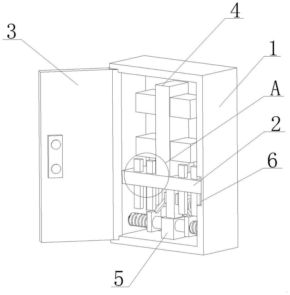
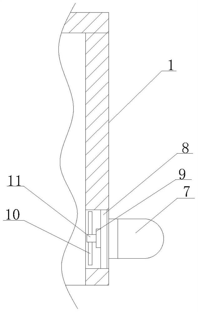
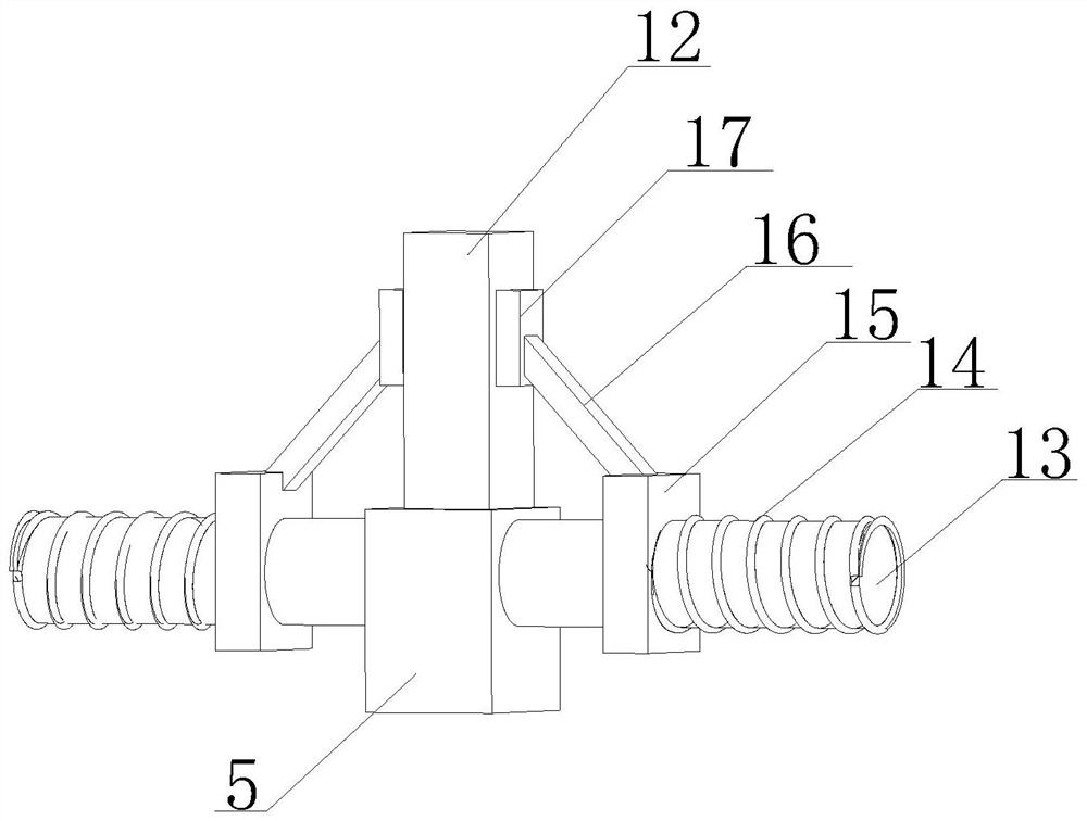
[0025] Such as Figure 1-5 As shown, the present invention provides a novel low-voltage switchgear with shockproof and heat dissipation, the switchgear main body 1, the left end of the switchgear main body 1 is provided with a movable shaft, and the outside of the movable shaft is fixedly connected with a switchgear door plate 3, and the switchgear door plate 3 The set movable shaft is movably connected with the main body 1 of the switchgear. The inside of the main body 1 of the switchgear is provided with a support plate 2. The upper end of the support plate 2 is fixedly connected with a support element 4. The outside of the support element 4 is fixedly connected with electronic components. The switchgear The inner bottom of the main body 1 is fixedly connected with a shock-absorbing base 5, and the upper end of the shock-absorbing base 5 is provided with a connecting rod 12, the back of the switch cabinet main body 1 is provided with a heat dissipation pipe 7, and the right e...
Embodiment 2
[0027] Such as Figure 1-5 As shown, on the basis of Embodiment 1, the present invention provides a technical solution: preferably, a movable element is arranged inside the fixed block 17, and the right end of the movable element is fixedly connected with the left end of the movable rod 16 provided, and the damping spring 14 The right end of the right end is fixedly connected with the inner wall of the switch cabinet main body 1 provided, and the slider 15 is fixedly connected with the inner wall of the switch cabinet main body 1 through the set damping spring 14. The bottom end is fixedly connected with a support spring 18, and the setting of the shock-absorbing base 5, the connecting rod 12 and the support spring 18 can squeeze the support spring 18 under the situation that the gravity of the upper end increases and shakes, so as to play the role of shock absorption and buffering. Effect, avoiding that the gravity is large, causing damage to the device, the upper end of the ...
Embodiment 3
[0029] Such as Figure 1-5 As shown, on the basis of Embodiment 1, the present invention provides a technical solution: preferably, the inner wall of the switchgear main body 1 is provided with a chute 6, and the right end of the support plate 2 is matched with the chute 6 provided, and supports The plate 2 slides up and down along the chute 6, the middle part of the support plate 2 is provided with a heat-conducting plate 19, the inside of the switchgear main body 1 is provided with a through hole, and the inside of the through hole is fixedly connected with a cross support rod 8, and the cross The left end of the support rod 8 is fixedly connected with a motor 9, and the left end of the motor 9 is movably connected with a fan shaft 11, and the outside of the fan shaft 11 is fixedly connected with a fan blade 10, a support plate 2, a support element 4 and a thermally conductive sheet 19. During the working process of the switch cabinet, the heat dissipated inside the switch c...
PUM
 Abstract
Description
Claims
Application Information