Blood cell analyzer

A blood cell analysis and diluent technology, which is applied in the field of medical equipment, can solve the problems of high cost, large gas consumption, and large volume, and achieve the effects of reducing the demand for gas consumption, miniaturization and low cost, and reducing volume and cost

Pending Publication Date: 2022-03-01
SHENZHEN MINDRAY BIO MEDICAL ELECTRONICS CO LTD
View PDF0 Cites 3 Cited by
  • Summary
  • Abstract
  • Description
  • Claims
  • Application Information

AI Technical Summary

Problems solved by technology

[0008] The purpose of the present invention is to provide a blood cell analyzer, which aims to solve the technical problems of large gas consumption, large volume and high cost in the existing blood cell analyzer

Method used


Image

  • Blood cell analyzer
  • Blood cell analyzer
  • Blood cell analyzer

Examples


Embodiment 1

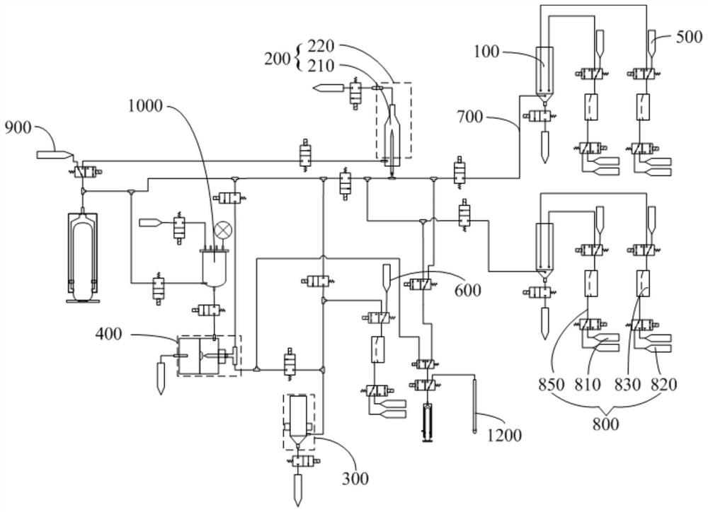
[0050] Such as Figure 1-5 As shown, the blood cell analyzer provided by Embodiment 1 of the present invention includes an optical channel reaction cell 100, an optical detection unit 200, a hemoglobin detection unit 300, an impedance counting detection unit 400, a first reagent supply device 500, and a second reagent supply device 600, delivery pipeline assembly 700, fluid power device 800, diluent supply device 900, diluent reservoir 1000, sampling component 1200 and impedance counting detection sample preparation unit (in this embodiment, the hemoglobin detection unit 300 also serves as an impedance counting The detection sample preparation unit is used, that is, the impedance counting detection sample preparation unit and the hemoglobin detection unit 300 are integrated). Sampling part 1200, optical detection unit 200, optical channel reaction cell 100, impedance counting detection sample preparation unit, hemoglobin detection unit 300, impedance counting detection unit 40...

Embodiment 2

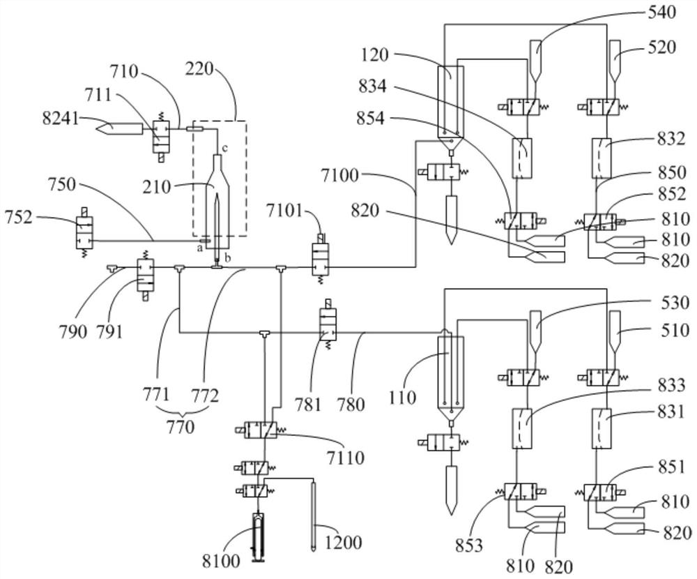
[0135] refer to Figure 4-7 As shown, the difference between the blood cell analyzer provided in this embodiment and the first embodiment mainly lies in: the structural solutions of the positive pressure supply unit 810 and the negative pressure supply unit 820 are different. In the first embodiment, both the positive pressure supply unit 810 and the negative pressure supply unit 820 include air chambers; however, in this embodiment, the air chambers of the positive pressure supply unit 810 and the negative pressure supply unit 820 are eliminated, that is, the positive pressure supply unit 810 does not Including the positive pressure air chamber, the negative pressure providing unit 820 does not include the negative pressure air chamber.

[0136] In this embodiment, one port of the first air pump 811 is connected to the atmospheric pressure, and the other port is connected to the positive pressure output pipeline 815 through the first positive pressure control valve 813, and t...

Embodiment 3

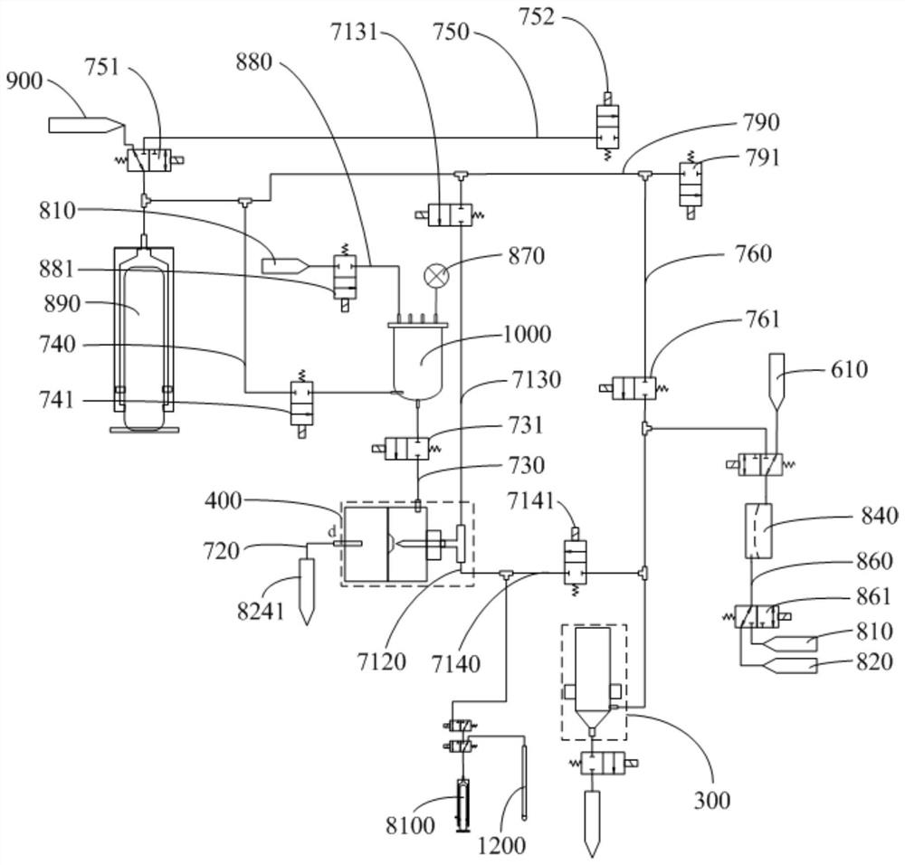
[0141] refer to Figure 4 , Figure 5 , Figure 8 and Figure 9 As shown, the difference between the blood cell analyzer provided in this embodiment and the first embodiment mainly lies in that the settings of the first voltage stabilizing component 814 and the second voltage stabilizing component 824 are different. In the first embodiment, the first pressure stabilizing component 814 is a positive pressure air chamber; the second stabilizing component 824 is a negative pressure air chamber; and in this embodiment, the first stabilizing component 814 is a first gas storage tube; Part 824 is the second air storage pipe, that is, the present embodiment is equivalent to canceling the setting of the positive pressure air chamber and the negative pressure air chamber, and replacing the air chamber with a section of air pipe.

[0142] In this embodiment, one port of the first air pump 811 is connected to atmospheric pressure, and the other port is connected to the first gas stora...


PUM


Abstract

The invention is applicable to the field of medical equipment, and discloses a blood cell analyzer. The device comprises a sampling part, an optical channel reaction tank, an optical detection unit, a hemoglobin detection unit, an impedance counting detection sample preparation unit, an impedance counting detection unit, a first reagent supply device, a second reagent supply device, a diluent supply device, a conveying pipeline assembly and a fluid power device, the sampling part, the optical detection unit, the optical channel reaction tank, the hemoglobin detection unit, the impedance counting detection sample preparation unit, the impedance counting detection unit, the first reagent supply device, the second reagent supply device, the diluent supply device and the fluid power device are connected through the conveying pipeline assembly to form a liquid path system; the average gas consumption of the liquid path system is less than or equal to 2.0 L/min in a detection period of completing hemoglobin detection, impedance counting detection and optical detection, so that the miniaturization and low-cost design of the instrument is realized.

Description

technical field [0001] The invention relates to the field of medical equipment, in particular to a blood cell analyzer. Background technique [0002] Five-differentiation hematology analyzers generally include a fluid power device, which is mainly used to provide power for the delivery of samples and reagents to achieve measurement. In the prior art, the design schemes of fluid power devices mainly include the following types: [0003] 1) The fluid power device adopts an external air source scheme that can provide a large flow rate: this scheme that uses an external air source as a power source can provide high pressure and large flow rate (generally provide no-load flow rate greater than 10L / min, Pressure above 200kPa) can drive cylinders, pneumatic pressure cut-off valves, pneumatic quantitative pumps, etc. The speed is fast, and it can support high air consumption parts to work at the same time (the average air consumption of the whole machine is more than 5L / min), so t...

Claims


Application Information

Patent Timeline
Patent Type & Authority Applications(China)
IPC IPC(8): G01N15/00G01N15/06G01N33/487G01N33/49G01N21/64G01N21/05
CPCG01N15/00G01N15/06G01N15/0656G01N33/48707G01N33/4915G01N21/6428G01N21/05G01N2015/0065G01N2015/0693
Inventor 石汇林滕锦李晓强
Owner SHENZHEN MINDRAY BIO MEDICAL ELECTRONICS CO LTD
Why Eureka
Try Eureka