U-shaped pressing die for scaffold eye plate

A scaffolding and eye plate technology, applied in the field of compression molding devices, can solve the problems of low efficiency and the inability to achieve the strength of stainless steel eye plates, etc., and achieve the effect of reducing work intensity and increasing work efficiency

CN114192629APending Publication Date: 2022-03-18CHENGXI SHIPYARD
0 Cites 0 Cited by

Patent Information

Authority / Receiving Office
CN · China
Patent Type
Applications(China)
Current Assignee / Owner
Publication Date
2022-03-18

Smart Images

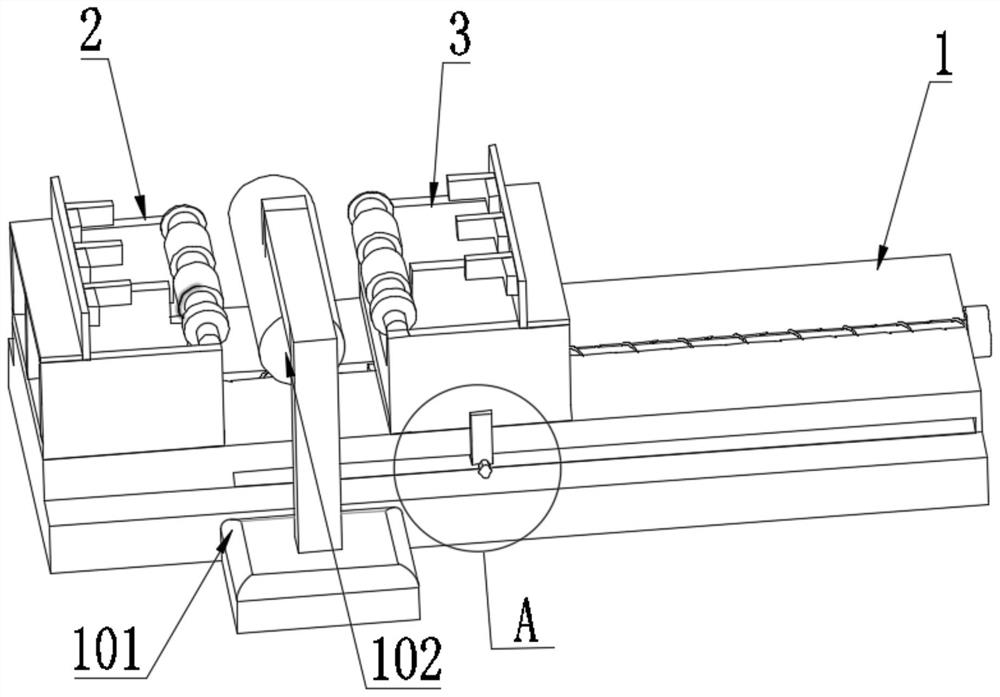
  • Figure 1
    Figure 1
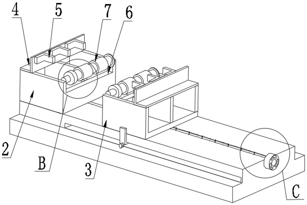
  • Figure 2
    Figure 2
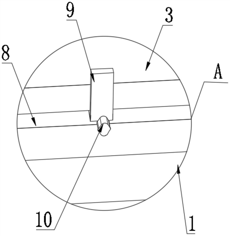
  • Figure 3
    Figure 3
Patent Text Reader

Abstract

The scaffold eye plate U-shaped pressing die comprises a machining table and a hydraulic vehicle, the hydraulic vehicle is arranged on one side of the front face of the machining table, an upper die is detachably installed at the top end of the hydraulic vehicle, a first lower die is fixedly installed at one end of the top of the machining table, and a second lower die is movably installed on the upper surface of the machining table; the other end of the screw rod is fixedly connected with a flange; by adjusting the first lower die and the second lower die, the distance between the limiting grooves in the peripheries of the limiting blocks on the two sides is matched with the distance between the to-be-machined U-shaped scaffold eye plates, the two ends of stainless steel round steel are positioned through the fixing bases and the fixing blocks, and the situation that in the pressurizing process, the stainless steel round steel is extruded and shifted, and consequently pressurizing rolling is caused is prevented; and the hydraulic vehicle drives the upper die to pressurize the middle parts of the symmetrically placed stainless steel round steel, so that the working intensity of constructors is reduced, and the problems that the scaffold eye plate is manually bent, the efficiency is low, and the device is only suitable for bending the carbon steel round steel are solved.
Need to check novelty before this filing date? Find Prior Art

Description

technical field

[0001] The invention relates to the technical field of compression molding devices, in particular to a U-shaped compression mold for a scaffold eye plate. Background technique

[0002] Scaffold eye plates are usually used on large oil tankers, and the scaffold eye plates of finished oil tankers are all made of stainless steel. The stainless steel round steel needs to be bent into a U shape. The traditional method is to burn the round steel red with a cutter, and then manually Manual bending is carried out on the mould, and the formed U-shaped scaffold eye plate is less efficient.

[0003] In the prior art, scaffold eye plates are bent manually, which is not only inefficient, but also only suitable for bending round steel made of carbon steel, and the stainless steel eye plates of finished cruise ships cannot reach the strength of stainless steel eye plates. Contents of the invention

[0004] The purpose of the present invention is to provide a U-shaped die...

Examples

Embodiment Construction

[0023] The following will clearly and completely describe the technical solutions in the embodiments of the present invention with reference to the accompanying drawings in the embodiments of the present invention. Obviously, the described embodiments are only some, not all, embodiments of the present invention. Based on the embodiments of the present invention, all other embodiments obtained by persons of ordinary skill in the art without making creative efforts belong to the protection scope of the present invention.

[0024] see Figure 1-5 , the present invention provides a technical solution: scaffold eye plate U-shaped die, including processing table 1, hydraulic car 101, the front side of processing table 1 is provided with hydraulic car 101, hydraulic car 101 is fixedly connected to the ground by bolts, hydraulic car The top end of 101 is detachably installed with an upper mold 102 by bolts, the top end of the processing table 1 is fixed with a first lower mold 2 by bo...