Material collecting device and image-text cutting machine

A technology of receiving device and cutting area, which is applied in the cutting of textile materials, textile and papermaking, metal processing, etc., which can solve the problems of fabric wrinkles and low efficiency, and achieve the effects of avoiding wrinkles, improving reliability, and improving versatility

Active Publication Date: 2022-04-05
NINGBO JINGWEI SYSTEMTECHNIK LTD
View PDF9 Cites 2 Cited by
  • Summary
  • Abstract
  • Description
  • Claims
  • Application Information

AI Technical Summary

Problems solved by technology

[0003] However, when the cloth is cut, in the process of receiving the material, one way is to collect the material manually, which is inefficient, and it is easy to cause wrinkles in the material during the receiving process, and the other way is to grab it by the robot, but the robot During the grabbing process, the generally grabbed part is the center of the fabric, which causes the fabric to appear "high in the middle and drooping around" when the fabric is collected and transferred, and it is also easy to cause fabric wrinkles

Method used


Image

  • Material collecting device and image-text cutting machine
  • Material collecting device and image-text cutting machine
  • Material collecting device and image-text cutting machine

Examples


Embodiment 1

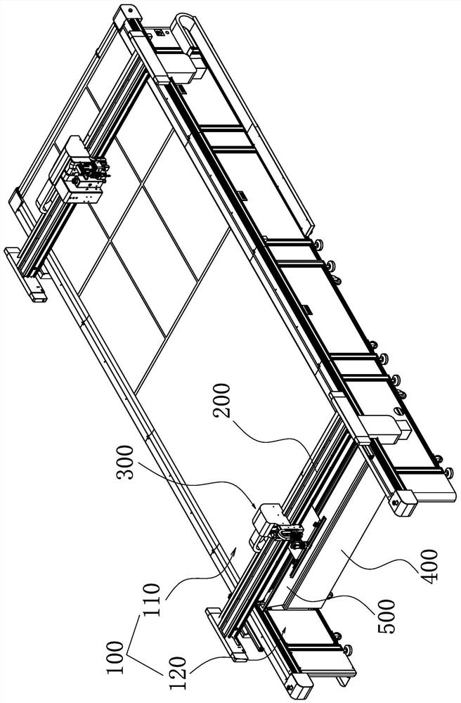
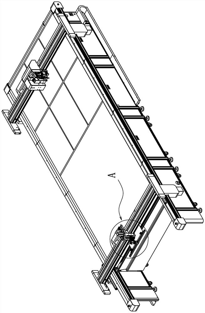
[0043] Such as Figure 1 to Figure 10 ,as well as Figure 14 As shown, a kind of receiving device provided by the present invention includes:

[0044] The frame 100 is sequentially provided with a cutting area 110 and a receiving area 120 along the conveying direction of the cloth;

[0045] The gantry 200 spans both sides of the frame 100 and is connected to both sides of the frame 100, wherein the gantry 200 can slide along the length direction of the frame 100;

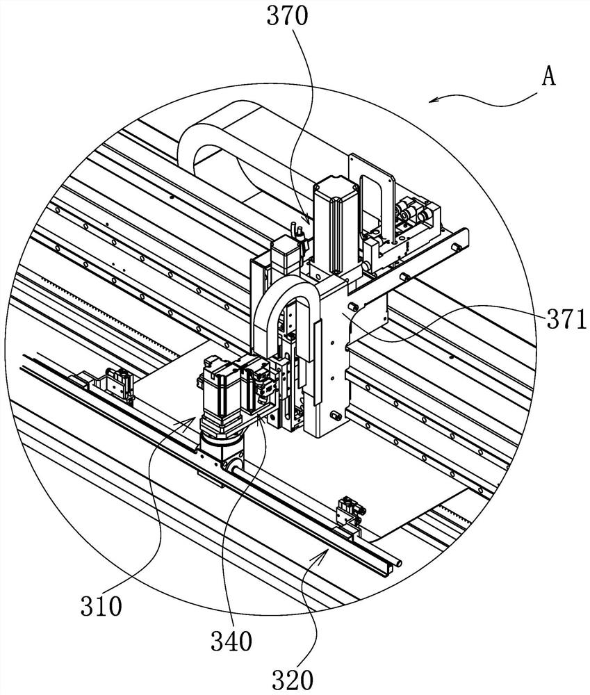
[0046] The receiving assembly 300 is installed on the gantry 200, and the cut cloth in the cutting area 110 is transferred to the receiving area 120 through the receiving assembly 300, wherein the receiving assembly 300 includes a driving structure 310, and the driving structure 310 includes a drive motor 311, the output end of the drive motor 311 is connected to a reducer 312, wherein, the output end of the reducer 312 is connected to a bidirectional screw rod 313, and two grabbing parts are screwed on the bidire...

Embodiment 2

[0069] Such as Figure 1 to Figure 14 As shown, the difference between this embodiment and the first embodiment is that the two grasping parts 314 in this embodiment are not set in linkage, and two receiving assemblies 300 are arranged on the gantry 200, In the receiving assembly 300 at this time, the driving structure 310 and the rotating structure 340 can be omitted, and the grasping part 314 is directly connected to the knife seat connecting plate 355 of the lifting structure 350 . However, if the two gripping parts 314 are arranged separately, the flexibility is better.

[0070] It should be noted that, in the present invention, descriptions involving "first", "second", "one" and so on are only for descriptive purposes, and should not be understood as indicating or implying their relative importance or implicitly indicating The number of technical characteristics. Thus, the features defined as "first" and "second" may explicitly or implicitly include at least one of thes...


PUM


Abstract

The invention provides a material collecting device and an image-text cutting machine, and belongs to the technical field of cutting. The material collecting device comprises a rack, and a cutting area and a material collecting area are arranged on the rack; the portal frame stretches across the two sides of the rack, and the portal frame can move in the length direction of the rack; and the material receiving assembly is installed on the portal frame, the cut cloth in the cutting area is transferred into the material receiving area through the material receiving assembly, and the material receiving assembly comprises two grabbing parts capable of synchronously moving oppositely or oppositely or comprises two grabbing parts capable of independently moving. According to the cloth collecting device, the two grabbing parts synchronously grab the two sides of cut cloth in the cutting area, the cloth is transferred to the collecting area from the cutting area along with movement of the portal frame, cloth collecting is completed, the cloth is always in a flat state in the transferring process, the wrinkle phenomenon is avoided, and the cloth collecting reliability is improved.

Description

technical field [0001] The invention belongs to the technical field of cutting, and relates to a material receiving device and a picture-text cutting machine. Background technique [0002] As an important processing raw material for clothing, sheets, packaging bags, and rags, cloth is widely used in social production. At present, the processed fabric is usually wound on the drum, and people need to use scissors to cut it when taking the material, and use a ruler to cooperate with it when cutting, so as to prevent the scissors from walking along the curve when cutting, resulting in waste of fabric, and the operation is troublesome and laborious. , Sometimes two people are required to carry out at the same time, resulting in a waste of manpower. Therefore, people invented the cloth cutting machine, which can cut the cloth automatically by using the machine, which greatly shortens the time of cutting cloth and avoids the trouble of manual operation. This kind of cloth cutting ...

Claims


Application Information

Patent Timeline
Patent Type & Authority Applications(China)
IPC IPC(8): D06H7/00B26D7/32
Inventor 卿永洲王鹏旭黄川波朱刚峰
Owner NINGBO JINGWEI SYSTEMTECHNIK LTD
Why Eureka
Try Eureka