

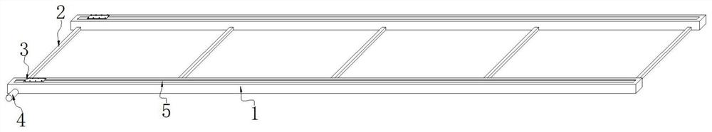
Transverse moving mechanism of portal crane
A technology of gantry crane and traverse mechanism, which is applied in the directions of traveling mechanism, mechanical equipment, transmission parts, etc., can solve the problems of unfavorable safety, reduced equipment service life, damage of guide rails and clamping wheels, etc., to avoid inconsistent moving distance, The effect of preventing rainwater erosion and ensuring service life
- Summary
- Abstract
- Description
- Claims
- Application Information
AI Technical Summary
Problems solved by technology
Method used
Image

Examples
Embodiment approach
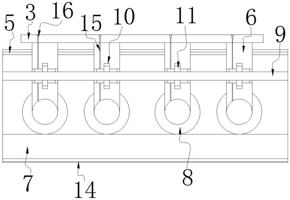
[0030] As a preferred embodiment of the present invention, the inner side of the clamping plate 11 is provided with internal threads, and the outer side of the screw rod 9 is provided with external threads, and the internal threads cooperate with the external threads.
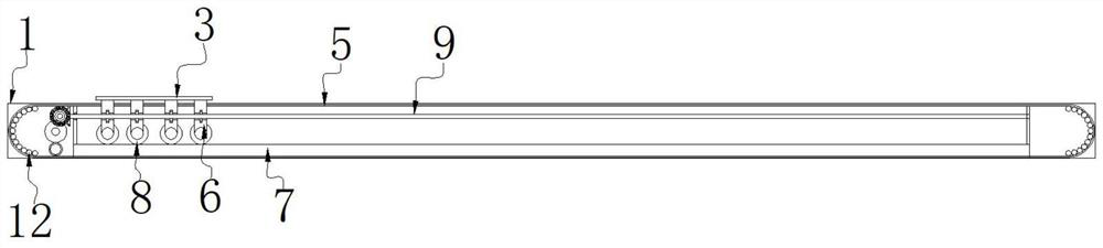
[0031] As a preferred embodiment of the present invention, the inner sides of both ends of the clamping chamber 10 are bonded with sealing sleeves, and the sealing sleeves are set on the outer side of the screw rod 9. When the screw rod 9 rotates, the screw rod 9 passes through the screw thread. Push the clamping plate 11 to move laterally, and then make the clamping plate 11 push the bracket 6 to move laterally through the clamping cavity 10, the bracket 6 moves on the top of the guide rail 7 through the card wheel 8, and then drives the gantry crane through the support 3 to move laterally, When the gantry crane and its hoisted weights cause a slight depression in the foundation, the support 3 is pushed downwar...
PUM
 Abstract
Description
Claims
Application Information