Self-lubricating mute gear and manufacturing process thereof

A self-lubricating, gear technology, applied in gear lubrication/cooling, belt/chain/gear, components with teeth, etc., can solve the problems of reducing gear strength, difficult process, internal vibration, etc., to reduce wear rate, combine Good degree, good effect of compound degree

Pending Publication Date: 2022-04-12
苏州金亿精密齿轮有限公司
View PDF0 Cites 0 Cited by
  • Summary
  • Abstract
  • Description
  • Claims
  • Application Information

AI Technical Summary

Problems solved by technology

[0003] The existing high-speed gears usually include molded or metal gears. Due to the different shrinkage rates of various parts of molded plastic gears and abnormal mold values ​​may occur in any part, metal gears do not have the above disadvantages, but lack self-lubricating ability , and due to assembly problems, there will be internal vibration and noise. In actual use, in order to solve the lubrication problem of the gears, lubricating oil will be sprayed, but the lubricating oil cannot be increased in real time, and it will still cause serious internal wear. In some European and American countries Operations such as oil injection inside the gear are designed, but it is necessary to slot inside the gear, so that although oil can enter during use, the process is difficult due to slotting inside the gear, and the strength of the gear will be reduced

Method used


Image

  • Self-lubricating mute gear and manufacturing process thereof
  • Self-lubricating mute gear and manufacturing process thereof
  • Self-lubricating mute gear and manufacturing process thereof

Examples


Embodiment Construction

[0027] The following will clearly and completely describe the technical solutions in the embodiments of the present invention with reference to the drawings in the embodiments of the present invention.

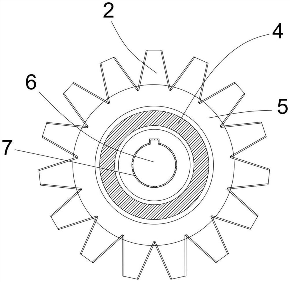
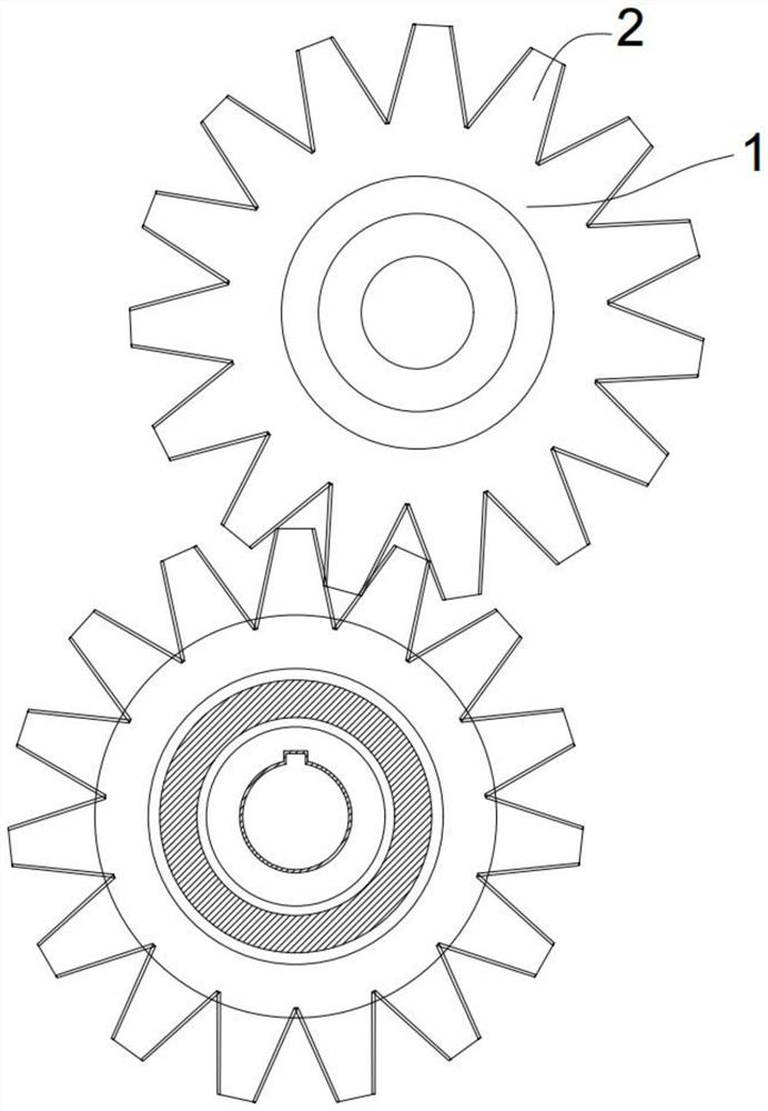
[0028] like figure 1 As shown, the present invention proposes a self-lubricating silent gear, which includes an annular body 1, and the circumference of the annular body 1 is integrally formed with a tooth body 2, and a nylon layer 3 is provided on the surface between the tooth bodies 2. The surface between the 2 is the contact surface of the tooth body 2 when the gears mesh, and the nylon layer 3 is provided, while the annular body 1 and the tooth body 2 are metal materials commonly used for gears, which can be steel with quenched and tempered steel, Hardened steel, carburized and quenched steel and nitrided steel, etc., are provided with a positioning block 8 on the opposite surface of the tooth body 2, which is convenient to occlude and fix with the metal material during ny...


PUM

PropertyMeasurementUnit
thicknessaaaaaaaaaa

Abstract

The self-lubricating mute gear comprises an annular body, tooth bodies are integrally formed on the circumference of the annular body, the annular body and the tooth bodies are made of metal, and nylon layers are arranged on the faces between the tooth bodies; an annular oil cavity is formed in the center of the annular body, an oil uniformizing device is arranged around the oil cavity, and the preparation process comprises the steps of S1, blank taking and milling, and S2, mold injection molding; according to the gear, the oil cavity integrally formed with the gear body is formed, and the oil homogenizing device is arranged outside the oil cavity, so that when the gear runs at a high speed, lubricating oil can be sprayed out from the side wall in the oil cavity under the action of centrifugal force, is uniformly dispersed out through the umbrella-shaped oil guide sheet and slowly permeates into the gear body, and the lubricating oil can be uniformly dispersed out through the umbrella-shaped oil guide sheet; the gear can be lubricated in real time; nylon is compounded on the meshing face of the gear, it is guaranteed that the wear rate of the gear is reduced, and due to the fact that the gear is made of a metal material, the metal material is low in shrinkage rate, and precision can still be kept.

Description

technical field [0001] The invention relates to the field of gear manufacturing, in particular to a self-lubricating gear and a manufacturing process thereof. Background technique [0002] A gear is a mechanical element with gears on the rim that continuously mesh to transmit motion and power. The application of gears in transmission has appeared very early. At the end of the 19th century, the principle of generative gear cutting method and special machine tools and cutting tools using this principle appeared one after another. With the development of production, the stability of gear operation was paid more attention. [0003] The existing high-speed gears usually include molded or metal gears. Due to the different shrinkage rates of various parts of molded plastic gears and abnormal mold values ​​may occur in any part, metal gears do not have the above disadvantages, but lack self-lubricating ability , and due to assembly problems, there will be internal vibration and no...

Claims


Application Information

Patent Timeline
Patent Type & Authority Applications(China)
IPC IPC(8): F16H55/17F16H57/04B23P15/14
Inventor 陈骞
Owner 苏州金亿精密齿轮有限公司
Why Eureka
Try Eureka