Rope net bearing device for lead crossing erection

A wire and rope net technology, applied in the field of rope net support devices, can solve the problems of long construction period, potential electric shock safety hazards for personnel, and difficult construction, and achieve the effects of reducing operating costs, preventing environmental pollution, and avoiding jamming.

Pending Publication Date: 2022-06-28
PINGMEI SHENMA CONSTR ENG GROUP
View PDF0 Cites 0 Cited by
  • Summary
  • Abstract
  • Description
  • Claims
  • Application Information

AI Technical Summary

Problems solved by technology

[0002] The crossing erection of conductors is aimed at crossing power lines, railways, etc., which must adopt a power outage drop-off or erect a spanning frame. Due to the long time of erecting a spanning frame, when crossing a power line, it is difficult to coordinate a power line outage. method, the construction is difficult, there are problems such as potential safety hazards of electric shock and long construction period, so the study of the live crossing construction device, when the tension is erected, the use of the rope net crossing device can not only be effective when the new transmission line crosses the uninterrupted power line Solve the above difficulties, reduce the damage to the surrounding natural environment caused by the traditional live crossing construction, save the compensation costs for destroying farmland, and reduce the cost of crossing construction can also improve the economic and social benefits of the enterprise
[0003] However, the erection of conductors generally belongs to high-altitude operations. When adjusting and installing rope nets through ropes, the pulley device supporting the rope net is prone to jamming in the absence of lubrication. It leads to obstacles in the project and delays in the work. Therefore, it is extremely necessary to ensure the rapid and stable installation of the rope net

Method used


Image

  • Rope net bearing device for lead crossing erection
  • Rope net bearing device for lead crossing erection
  • Rope net bearing device for lead crossing erection

Examples


Embodiment Construction

[0031] The technical solutions in the embodiments of the present invention will be clearly and completely described below with reference to the accompanying drawings in the embodiments of the present invention. Obviously, the described embodiments are only a part of the embodiments of the present invention, but not all of the embodiments.

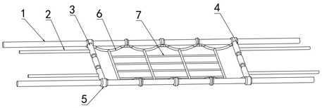
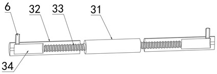
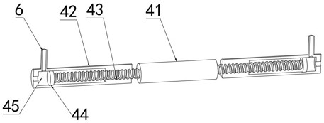
[0032] refer to Figure 1-8 , a rope net supporting device for the wire spanning erection, including a bearing cable 1, a first insulating strut 3 and a second insulating strut 4, the first insulating strut 3 and the second insulating strut 4 Both ends are fixedly installed with an adjusting pulley ring 5, a fixed rope 6 is also connected between the first insulating strut 3 and the second insulating strut 4, and an insulating rope net 7 is arranged between the fixed ropes 6 , the outer side wall of the fixed rope 6 is also provided with a plurality of sets of adjustment pulley rings 5, the adjustment pulley rings 5 ​​are movably sleeved on...


PUM


Abstract

The rope net bearing device comprises a bearing cable, a first insulation supporting rod and a second insulation supporting rod, adjusting pulley rings are fixedly installed at the two ends of the first insulation supporting rod and the two ends of the second insulation supporting rod, and a fixing rope is further connected between the first insulation supporting rod and the second insulation supporting rod. An insulating rope net is arranged between the fixing ropes, a plurality of groups of adjusting pulley rings are also arranged on the outer side walls of the fixing ropes, the outer side walls of the bearing cables are movably sleeved with the adjusting pulley rings, and the outer portions of the first insulating supporting rod and the second insulating supporting rod are further connected with adjusting traction ropes arranged in the same direction as the bearing cables; an oil storage groove is formed in the adjusting pulley ring. According to the device, the lubricating oil is automatically filled when the rope net is adjusted to work, it is guaranteed that the rope net is adjusted stably and orderly, real-time lubrication of a pulley mechanism in the bearing device is guaranteed, a large amount of maintenance and operation work is reduced, and it is guaranteed that the wire crossing erection work is stably conducted.

Description

technical field [0001] The invention relates to the technical field of electric power construction, in particular to a rope net supporting device for spanning and erecting wires. Background technique [0002] Conductor spanning erection is a construction method that must be used for crossing power lines, railways, etc., which must be powered off or set up spanning racks. Due to the long time of erecting spanning racks, power line power failure coordination is difficult when crossing power lines. Therefore, the live spanning construction device is studied, and the rope net spanning device is used when the new transmission line spans the uninterrupted power line when the new transmission line spans the uninterrupted power line, which can not only effectively Solving the above difficulties, reducing the damage to the surrounding natural environment caused by the traditional live spanning construction, saving the compensation costs for destroying farmland, and reducing the cost ...

Claims


Application Information

Patent Timeline
IPC IPC(8): H02G1/02F16N1/00F16N31/02
CPCH02G1/02F16N1/00F16N31/02
Inventor 刘军杰杨保民何坤安李向东郭保平李继刚程军卫雒超凡付元朝赵永吉林峰田冰冰樊明朝张志昂杜嘉俊李新立黄德甲
Owner PINGMEI SHENMA CONSTR ENG GROUP
Why Eureka
Try Eureka