Container transport and organizing apparatus for use in manufacturing operations and method thereof

a technology of transporting and organizing apparatus and manufacturing operations, applied in the direction of transportation and packaging, conveyors, conveyor parts, etc., can solve the problems of difficult to accommodate or adjust the tubes of varying sizes of these systems, high labor intensity of the process, and high cost of the robotic system, so as to achieve the effect of simple design and easy us

Inactive Publication Date: 2007-05-29
REAGENT CHEM & RES
View PDF9 Cites 16 Cited by
  • Summary
  • Abstract
  • Description
  • Claims
  • Application Information

AI Technical Summary

Benefits of technology

[0009]It is an object of the present invention to provide a new and useful tube loader or feeder that is simple in design and easy to employ.
[0011]Still a further object of the present invention is to provide a tube loader that is more ergonomic in construction.
[0012]Yet another object of the present invention is to provide a tube loader with a large adjustable feeding bin capacity so as to reduce the attendant time of an operator.
[0013]Still a further object of the present invention is to provide a method for processing bulk tubes into a sequential stream that is an improvement over existing processes.
[0020]With respect to the transfer assembly, it may include a rotatable transfer wheel that has a plurality of radially projecting prongs that are oriented to engage each of the selected containers and the sequentially transport each selected container to the intake location of the downstream conveyor assembly. Here, also, the transfer assembly can include a chute having a terminal end located proximately to the transfer wheel. The chute is adapted to receive containers from the reservoir and is dimensioned to allow single file passage of the containers therethrough. A shoe may be disposed at terminal end of the chute with the shoe adapted to position each selected container for engagement by the transfer wheel. The transfer assembly can include generally parallel first and second plate portions that form the chute. These first and second plate portions are spaced apart from one another a distance selected to allow single file passage of the containers therethrough. A first plate portion may also be reciprocally moveable in the upstream and downstream directions while the second plate portion may be laterally moveable so as to move toward and away from the first plate. The second plate can then include a sensor associated therewith to detect deflections of the second plate that are greater than a selected threshold. The transfer assembly can also include a paddle member pivotally disposed to the position to act on the containers in the reservoir, in an air-actuated cylinder is operative to reciprocally pivot the paddle member to prevent jamming of the containers when in the reservoir.

Problems solved by technology

Unfortunately, most of these tube-filling machines have a relatively small tube-feeding bin of only a few square feet in cross section.
On one hand, this process is very labor intensive and typically requires an operator to constantly attend the tube-filling machine.
Typically, these robotic systems are expensive.
Moreover, it is difficult for these systems to accommodate or adjust to tubes of varying sizes.

Method used


Image

  • Container transport and organizing apparatus for use in manufacturing operations and method thereof
  • Container transport and organizing apparatus for use in manufacturing operations and method thereof
  • Container transport and organizing apparatus for use in manufacturing operations and method thereof

Examples


Embodiment Construction

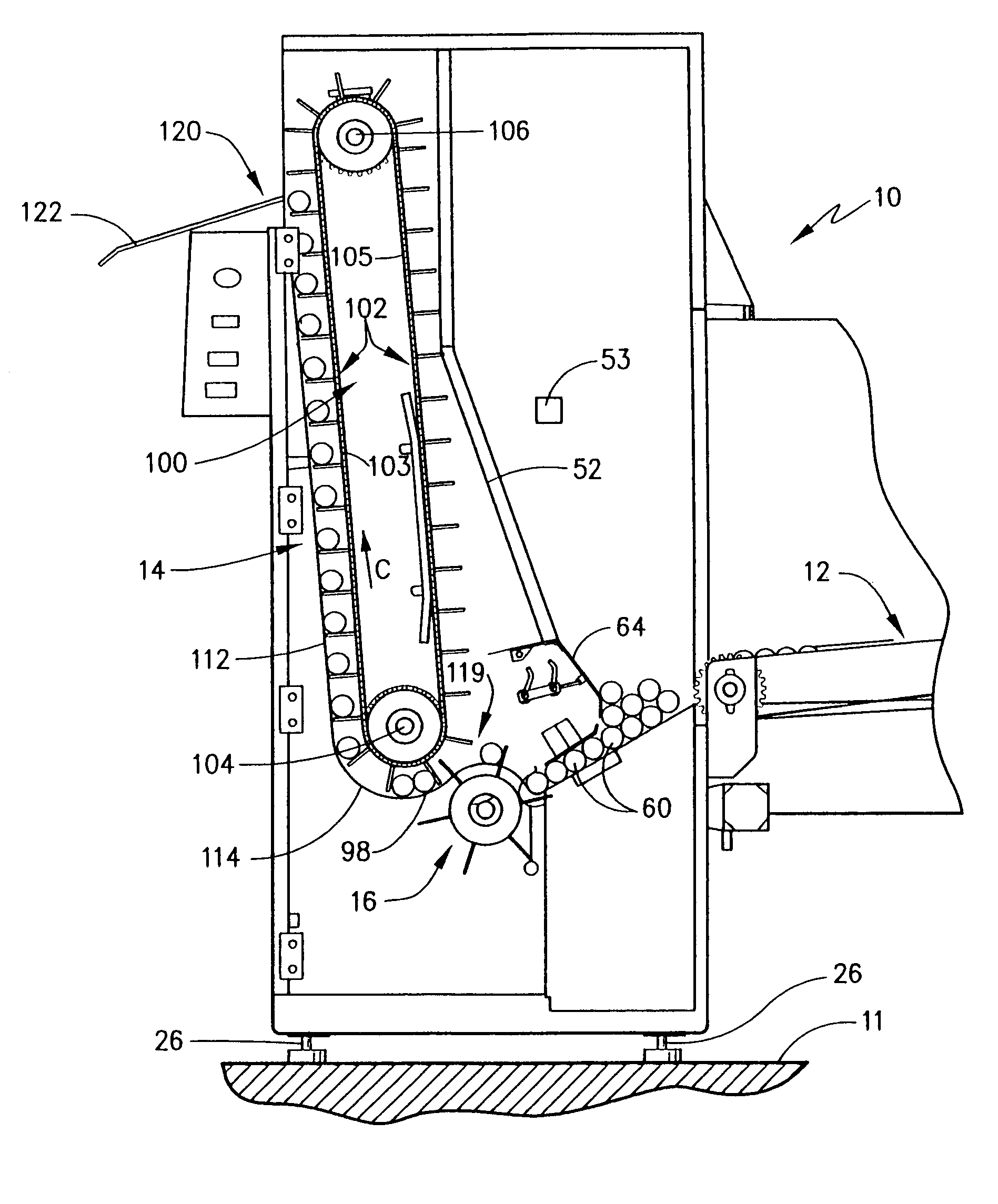
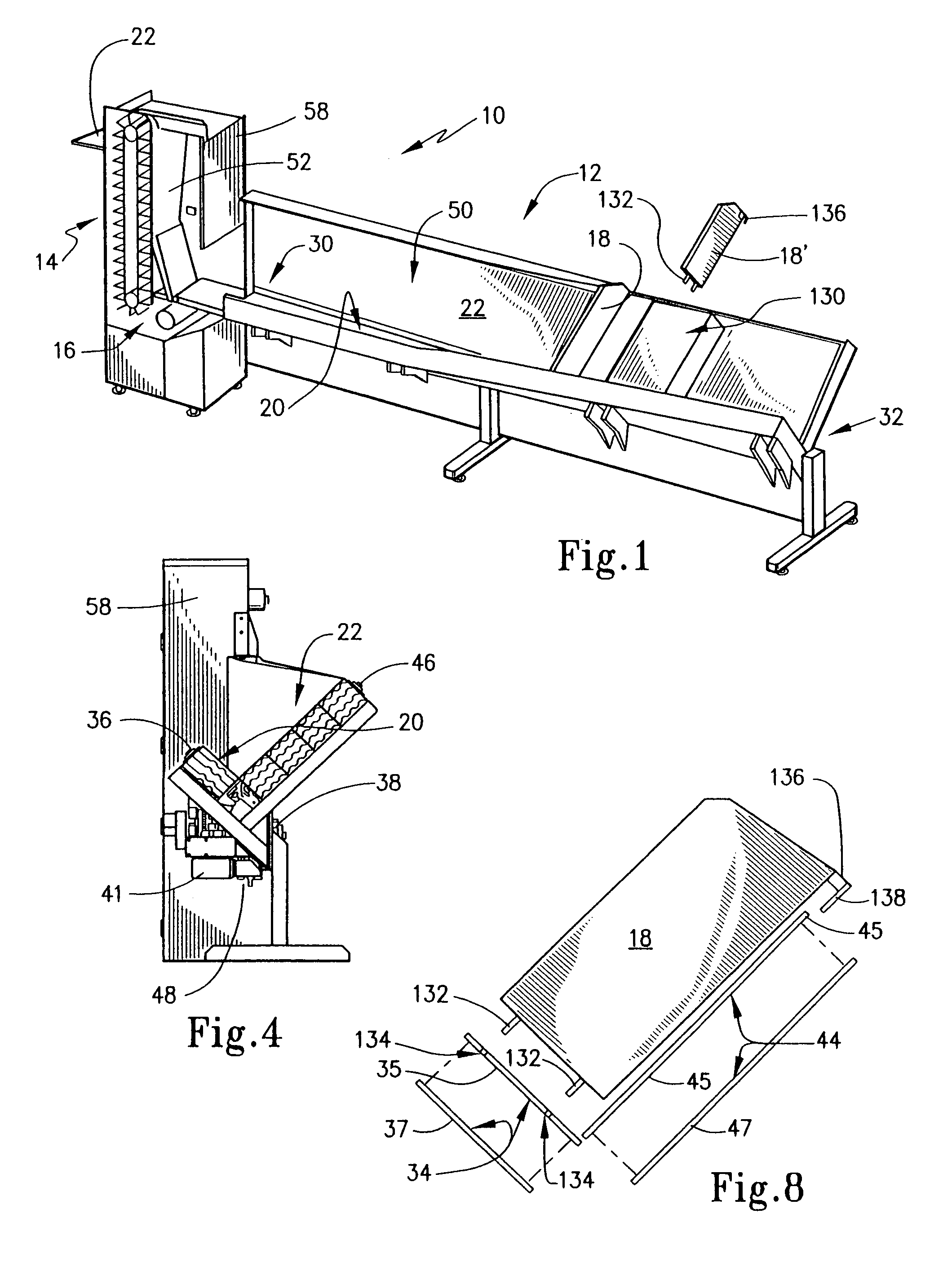
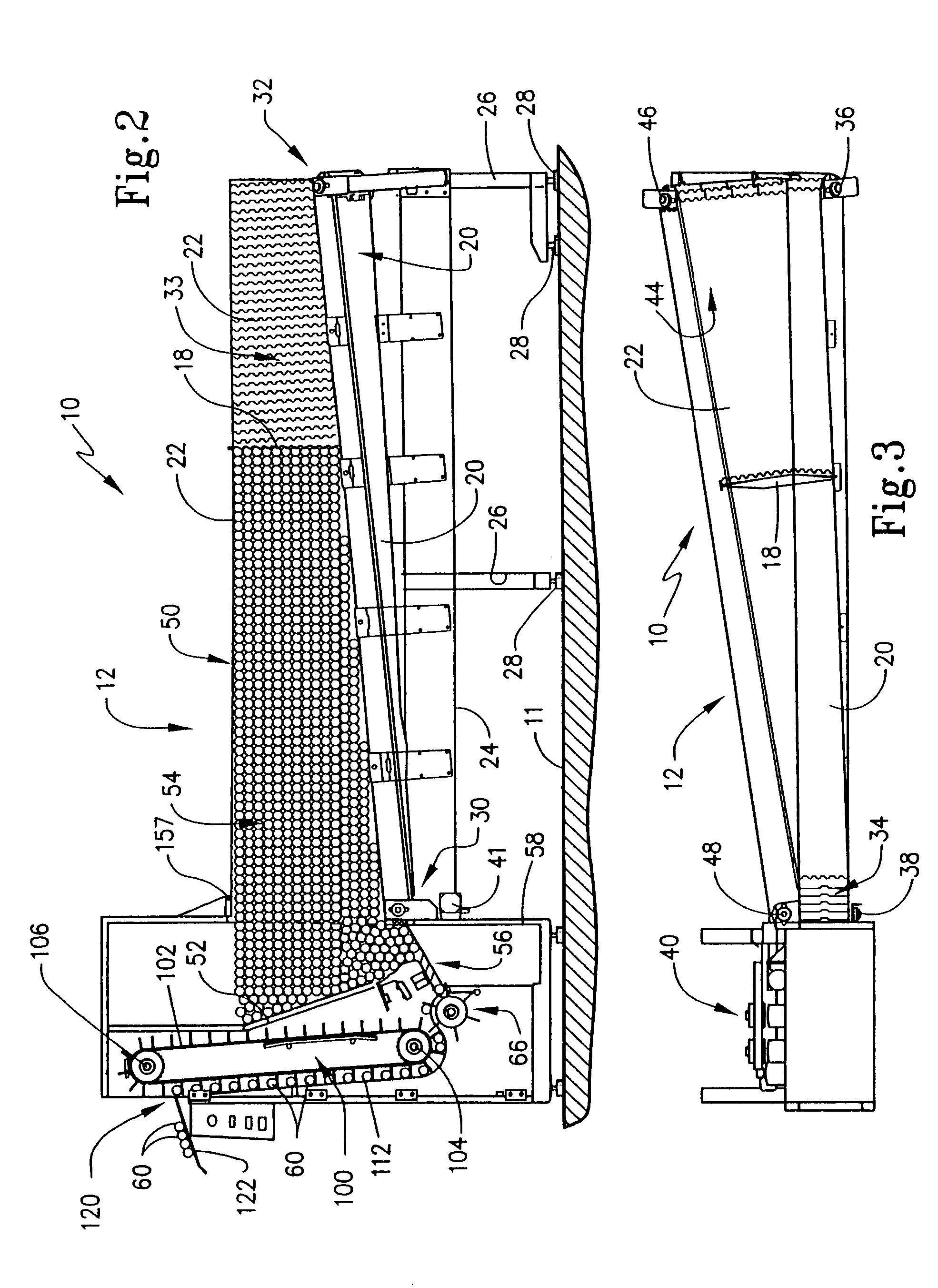
[0035]The present invention relates to a container transport and organizing apparatus in the form of a tube loader, also referred to as a tube feeder, which is able to receive bulk containers at a storage location and subsequently transports these containers in a sequential manner for further manufacturing operations, such as a filling operation. Accordingly, the present invention not only contemplates the mechanical structure of such an apparatus, but also the method that is inherent in the structure, all as described below. Moreover, it should be understood that, while the present invention is described with respect to cylindrical tubular containers, the ordinarily skilled artisan would be able to employ this process with containers of different shapes and configurations upon learning the structure and methods taught herein.

[0036]A first exemplary embodiment of a container transport and organizing apparatus according to the present invention, hereinafter referred to as a tube load...


PUM


Abstract

An apparatus and method for transporting containers to be processed in a manufacturing operation includes a transfer assembly that transfers containers from a load area on an upstream conveyor assembly to a discharge on downstream conveyor assembly for further processing. The upstream conveyor assembly may include longitudinally extending first and second conveyors oriented at an angle to one another. The transfer assembly may include a rotating wheel that picks containers from a chute and moves them, one at a time, to the downstream conveyor assembly. The downstream conveyor assembly may be in the form of an elevator that has bays that are sized to receive individual containers. The bays are formed by vanes on a moving belt. The method includes steps inherent in the structure, including receiving a bulk supply of containers, moving them horizontally, columnizing them into a single file, elevating them and thereafter discharging them.

Description

CROSS REFERENCE TO RELATED APPLICATIONS[0001]This application claims the benefit of U.S. Provisional Application No. 60 / 423,308 filed Nov. 1, 2002.FIELD OF THE INVENTION[0002]The present invention broadly relates to packaging equipment of the type used in automated processes. More particularly, the present invention is directed to manufacturing equipment that provides a supply of containers that may be subsequently filled and packaged for distribution. The invention specifically concerns tube-feeding mechanisms that can receive a bulk supply of containers and place them in a single file stream such that they may then be accessed by other equipment in the packaging process.BACKGROUND OF THE INVENTION[0003]The packaging of products for storage and consumption is a significant global industry. Various known packages include cartons, boxes, cans, tubes, pouches, to name a few. Packaged products encompass virtually any type of product that is available for consumption from large applianc...

Claims


Application Information

Patent Timeline
Patent Type & Authority Patents(United States)
IPC IPC(8): B65G47/30B65G47/14B65G47/57
CPCB65G47/1457B65G47/57B65G2201/0235
Inventor SHACKELFORD, MICHAEL L.SONNTAG, DONALD W.
Owner REAGENT CHEM & RES
Why Eureka
Try Eureka