Device convenient for positioning pedicle screw
A pedicle screw, a convenient technology, applied in the field of medical devices, can solve the problems of easily causing medical accidents, positioning devices and systems rely on navigation functions, and lack of physical depth-limiting functions, etc., to achieve reasonable structure, improve success rate, and ensure safety Effect
- Summary
- Abstract
- Description
- Claims
- Application Information
AI Technical Summary
Problems solved by technology
Method used
Image

Examples
Embodiment 1
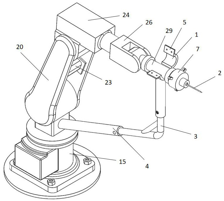
[0057] Please refer to Figure 1-14 , a device for conveniently positioning pedicle screws in this embodiment, which includes a mechanical arm, a depth-limiting structure, a target structure 2, and a fixed clamping structure; the first end of the depth-limiting structure is fixed on the first end of the mechanical arm, and the depth-limiting structure The second end of the deep structure is movably connected to the second end of the mechanical arm; the fixed clamping structure is fixedly connected to the mechanical arm; and the target structure 2 is detachably connected to the fixed clamping structure. This setting installs the original gripping target structure 2 to the fixed clamping structure and integrates it into the robotic arm. Measure the length of the vertebral body from the nail entry point to the front edge of the vertebral body according to the planned navigation of the robotic arm. The setting is smaller than this value. The depth-limiting structure can ensure the...
Embodiment 2
[0059] Please refer to figure 1 , 9. On the basis of Embodiment 1, this embodiment adds the following technical features: (the following specific settings are made to the depth-limiting structure): the depth-limiting structure includes two sections of telescopic rods and moving rings 1 integrally connected; Ring 1 is fixedly connected.
[0060] The two sections of telescopic rods respectively include an inner rod 3 and an outer sleeve 4, the outer sleeve 4 is located on the outside of the inner rod 3 and can slide relative to the inner rod 3; Reinforcing rods are arranged between the sides, and the angle between the two inner rods 3 is between 120° and 150°, which can ensure the limit strength of the telescopic rods.
[0061] At least one threaded hole is respectively provided on the sides of the two outer sleeves 4, and suitable bolts are installed in the threaded holes; this setting ensures that when the two sections of the telescopic rods are adjusted to a suitable length,...
Embodiment 3
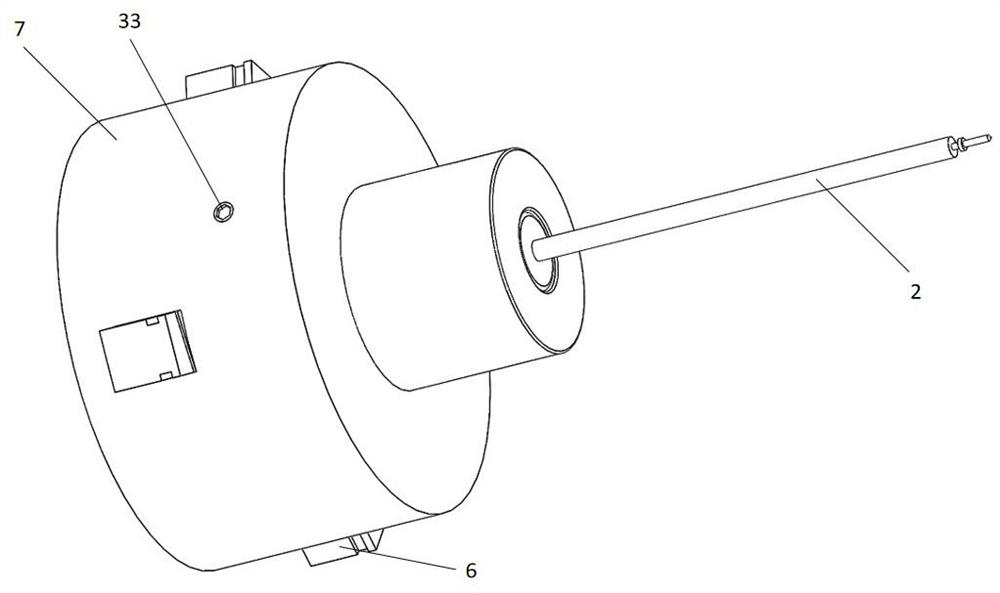
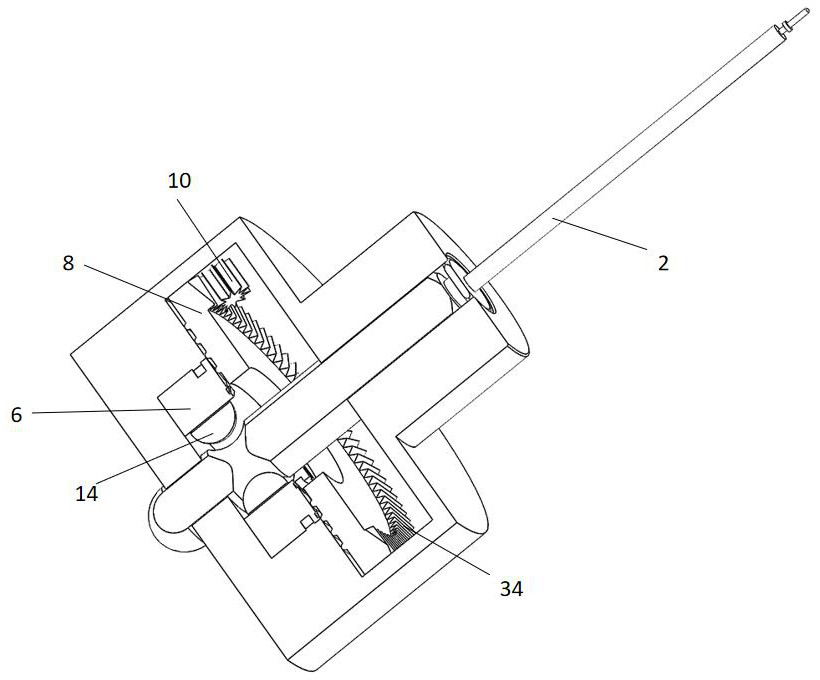
[0066] Please refer to Figure 1-8 , on the basis of Embodiment 1-2, this embodiment adds the following technical features (the following specific settings are made to the fixed clamping structure): the fixed clamping structure includes a clamping part and a clamping shell 7; the clamping shell 7 and the clamping part The center is provided with a channel to ensure the entry of the target structure 2; the clamping part is combined with the clamp shell 7, and the clamping part includes a plurality of clamping jaws 6 that can hold the target structure 2 tightly, and an operating structure that realizes the clamping and loosening of the clamping jaws 6 ; Drive the jaw 6 to grasp the target structure 2 by controlling the operation structure.
[0067] The clamp shell 7 is cylindrical, and the interior is a cylindrical cavity, which accommodates the operating structure and the jaws 6; this arrangement ensures the protection effect on the operating structure and the jaws 6.
[0068]...
PUM
 Abstract
Description
Claims
Application Information
 - R&D
- Intellectual Property
- Life Sciences
- Materials
- Tech Scout
- Unparalleled Data Quality
- Higher Quality Content
- 60% Fewer Hallucinations
Browse by: Latest US Patents, China's latest patents, Technical Efficacy Thesaurus, Application Domain, Technology Topic, Popular Technical Reports.
© 2025 PatSnap. All rights reserved.Legal|Privacy policy|Modern Slavery Act Transparency Statement|Sitemap|About US| Contact US: help@patsnap.com