

Liquid supply system and liquid supply method
A technology for liquid supply and waste liquid, which is applied to chemical instruments and methods, cleaning methods and utensils, and cleaning hollow objects, etc., which can solve the problems of long time consumption, low flushing force of special cleaning reagents on waste liquid pools, and long time for reagent distribution and other issues to achieve the effect of shortening the time
- Summary
- Abstract
- Description
- Claims
- Application Information
AI Technical Summary
Problems solved by technology
Method used
Image

Examples
Embodiment Construction
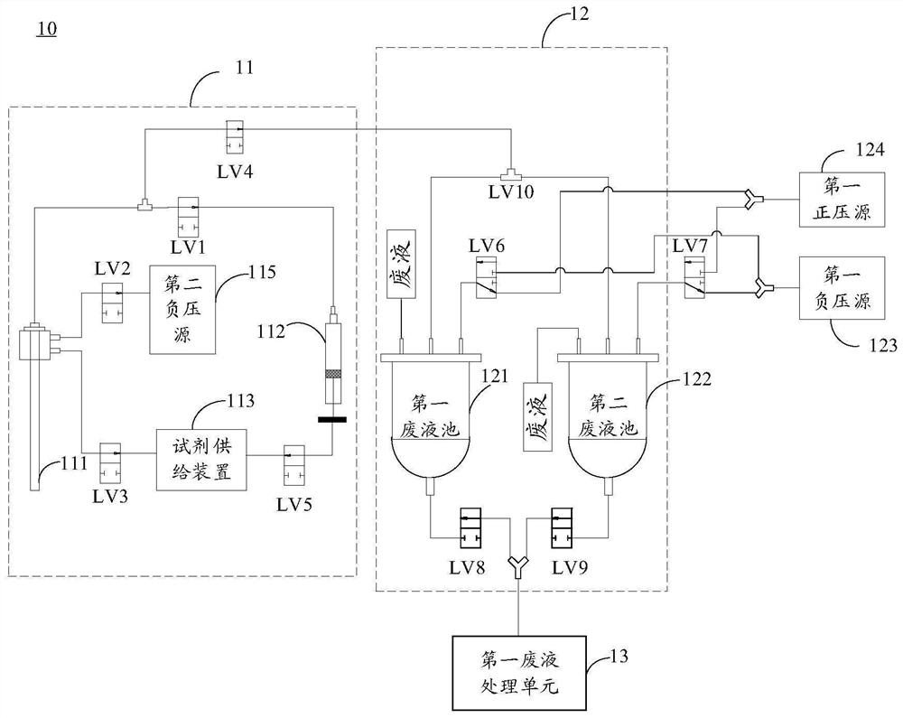
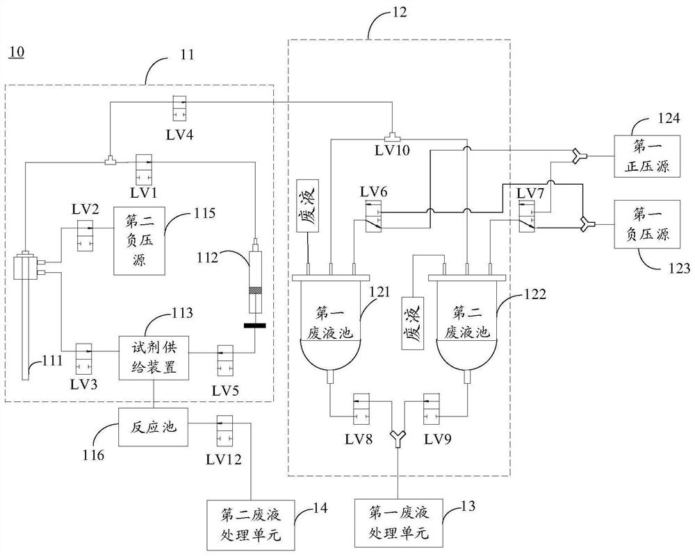
[0019] The technical solutions in the embodiments of the present application will be clearly and completely described below with reference to the accompanying drawings in the embodiments of the present application. Obviously, the described embodiments are only a part of the embodiments of the present application, but not all of the embodiments. The components of the embodiments of the present application generally described and illustrated in the drawings herein may be arranged and designed in a variety of different configurations. Thus, the following detailed description of the embodiments of the present application provided in the accompanying drawings is not intended to limit the scope of the claimed application, but is merely representative of selected embodiments of the present application. Based on the embodiments of the present application, all other embodiments obtained by those skilled in the art without creative work fall within the protection scope of the present app...
PUM
 Abstract
Description
Claims
Application Information