Supercharge Your Innovation With Domain-Expert AI Agents!

Connector capable of correcting position of connected object reliably

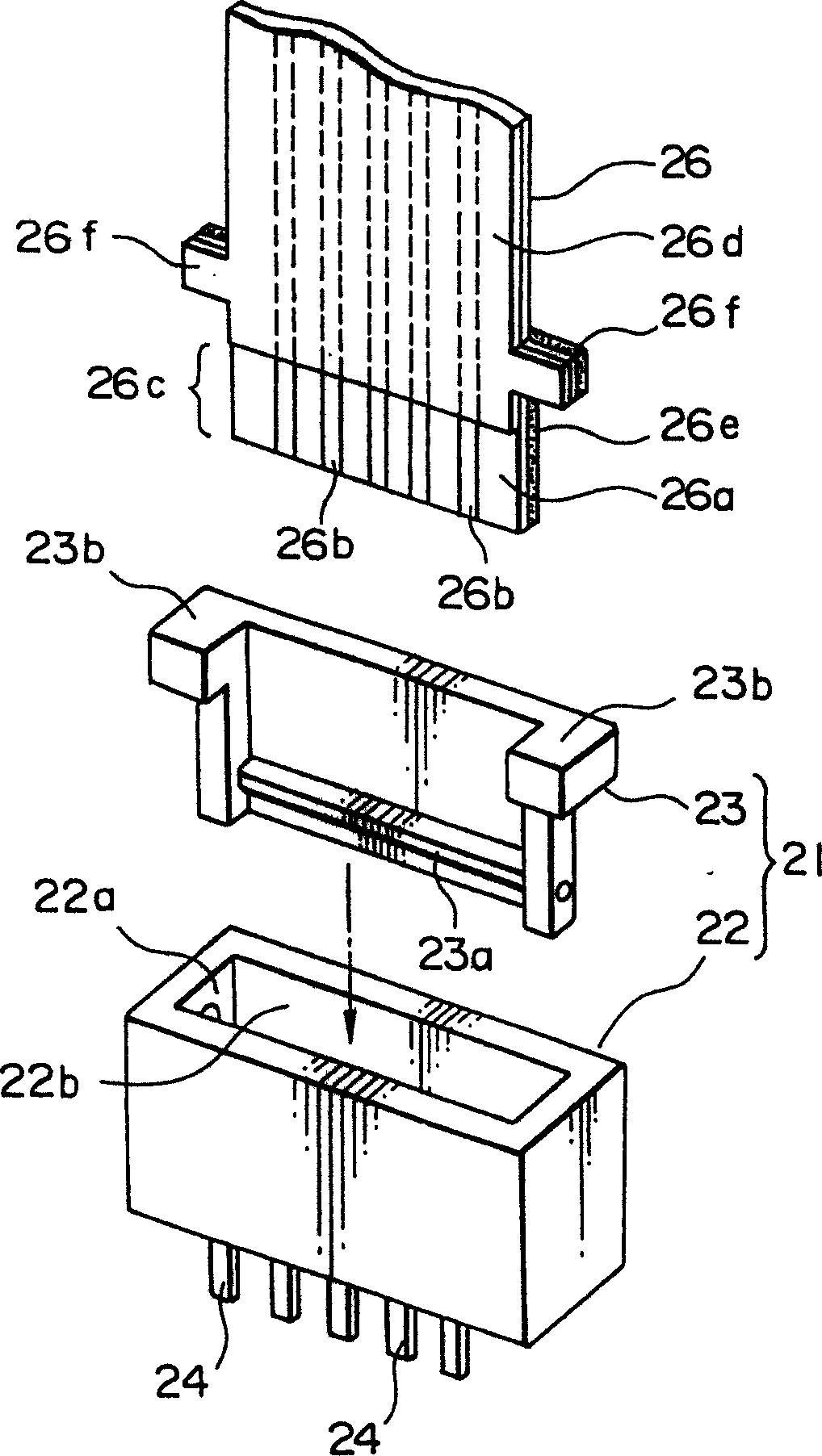
A technology of connectors and objects, which is applied to parts of connection devices, two-part connection devices, devices for preventing wrong connections, etc., can solve problems such as not being able to protect the front part of FPC26

Inactive Publication Date: 2005-02-02
JAPAN AVIATION ELECTRONICS IND LTD
View PDF1 Cites 1 Cited by
  • Summary
  • Abstract
  • Description
  • Claims
  • Application Information

AI Technical Summary

Problems solved by technology

[0014] However, in the second conventional technology, although the FPC inserted into the connector 21 hardly appears in a half-inserted state, the front end portion of the FPC 26 cannot be protected from unexpected external force.

Method used


Image

  • Connector capable of correcting position of connected object reliably
  • Connector capable of correcting position of connected object reliably
  • Connector capable of correcting position of connected object reliably

Examples


Embodiment Construction

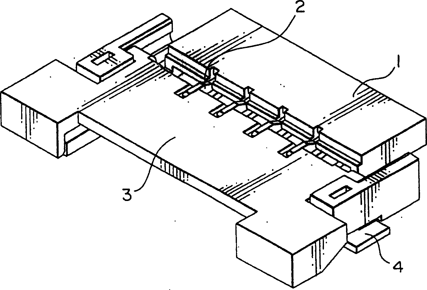
[0030] Refer to the following Figure 3-7 A connector of one embodiment of the present invention will be described.

[0031] Figure 3-7 The shown connector includes: an insulating housing 1; a plurality of conductive socket contacts 2, which are held by the housing 1 and arranged in a single-row matrix along a first direction A1. The housing 1 has an insulating actuator 3 rotatable between an open position and a closed position. Such as Figure 6 As shown, the actuator 3 has a pair of shafts 3a formed on opposite sides thereof and extending outward along a first direction A1. The shafts 3 a are rotatably supported by bearings (not shown) on opposite sides of the housing 1 , respectively, and serve as a rotation center of the actuator 3 . Thus, the actuator 3 can rotate in a predetermined direction, that is, the rotational direction A0 ( Figure 7 )sports. The bottom surface of the housing 1 is provided on opposite sides thereof with a pair of clamping plates 4 secured t...


PUM


Abstract

For connecting an object having protruding portions protruding reverse to each other in a first direction, a connector includes a housing for guiding the object to an inserted position in a second direction perpendicular to the first direction, a contact held by the housing, and an actuator movable in a predetermined direction with respect to the housing so as to bring the object into press contact with the contact. The housing has receiving portions for receiving the protruding portions, respectively. The actuator has cover portions to face the receiving portions and to cover the protruding portions, respectively, when the object is brought into press contact with the contact. The cover portions respectively having slant surfaces to be engaged with the protruding portions of the object, when the object is located at a position deviated from the inserted position, to force the object towards the inserted position following the movement of the actuator to bring the object into press contact with the contact.

Description

technical field [0001] The present invention relates to a connector for connecting objects such as a circuit board called a flexible printed circuit (FPC) and a cable called a flexible flat cable (FFC). Background technique [0002] First, a conventional technique disclosed in Japanese Unexamined Patent Publication No. 2000-299153 (JP2000-299153A) (hereinafter referred to as "first conventional technique") will be described with reference to FIGS. 1A to 1C. [0003] As shown in Figure 1B, a kind of connector 11 comprises: connector shell 12, it is contained on the printed wiring board with methods such as welding; , the other end is rotatable in the X and Y directions; 1C, the FFC 16 includes: a cable main body 17; a cable connecting portion 18 formed at one end of the cable main body 17; The cable locking protrusion 19 has a trapezoidal shape as a whole, and has a pair of triangular parts protruding laterally outward from the cable main body 17 on opposite sides thereof. ...

Claims


Application Information

Patent Timeline
Patent Type & Authority Patents(China)
IPC IPC(8): H01R13/639H01R13/64
CPCH01R12/88H01R12/7005H01R23/7005H01R23/684H01R13/64H01R12/79H01R13/639
Inventor 广濑久美
Owner JAPAN AVIATION ELECTRONICS IND LTD
Features
  • R&D
  • Intellectual Property
  • Life Sciences
  • Materials
  • Tech Scout
  • Unparalleled Data Quality
  • Higher Quality Content
  • 60% Fewer Hallucinations
Learn More