Continuous catalytic reforming and dehydrogenating reactor

A dehydrogenation reactor and catalytic reforming technology, which is applied in hydrotreating process, petroleum industry, processing of hydrocarbon oil, etc., can solve the problems of difficult installation and manufacturing, increase in volume of reforming reaction, adhere to the wall, etc., and achieve the elimination of static pressure. Poor difference, ensure uniform distribution, uniform effect of axial temperature

Inactive Publication Date: 2005-02-16
EAST CHINA UNIV OF SCI & TECH
View PDF7 Cites 0 Cited by
  • Summary
  • Abstract
  • Description
  • Claims
  • Application Information

AI Technical Summary

Problems solved by technology

The main disadvantage of this design is that it does not solve the fundamental problem of the occurrence of the above-mentioned "cavity" and "wall-attached" phenomena, and the reactor has a complex structure and is difficult to install and manufacture.
In the Chinese patent CN1258558A, the reactant material inlet is opened on the side of the reactor shell, and the vertical height of the reactant inlet is located in the middle of the axial height of the catalytic reaction zone. The reactant flows radially through the catalytic bed layer from outside to inside, and then enters the central gas collecting pipe. , and then flow out from the bottom of the reactor, so it is difficult to maintain the uniform distribution of the reactant flow along the axial direction, and it is easy to cause the phenomenon of "sticking to the wall"
In Chinese patent CN1127159A, the catalytic bed is divided by setting an intermediate wall in the catalyst bed in order to reduce the possibility of the catalyst sticking to the wall, but this method does not solve the fundamental problem of the catalyst sticking to the wall, but leads to a complex reactor structure
[0006] In summary, most of the various radial moving bed reactors adopt the centripetal flow mode of the reaction material from the outside to the inside along the radial direction, the radial gas presents an acceleration trend, and the reforming reaction is a process of increasing volume , therefore, in order to avoid "sticking to the wall", it brings great restrictions and difficulties to the design of the moving bed radial reactor
At the same time, the centripetal flow from the outside to the inside of the existing patented technology will inevitably cause the axial temperature difference of the catalytic bed due to the heat loss of the imported material in the outer split flow channel.

Method used


Image

  • Continuous catalytic reforming and dehydrogenating reactor
  • Continuous catalytic reforming and dehydrogenating reactor
  • Continuous catalytic reforming and dehydrogenating reactor

Examples


Embodiment Construction

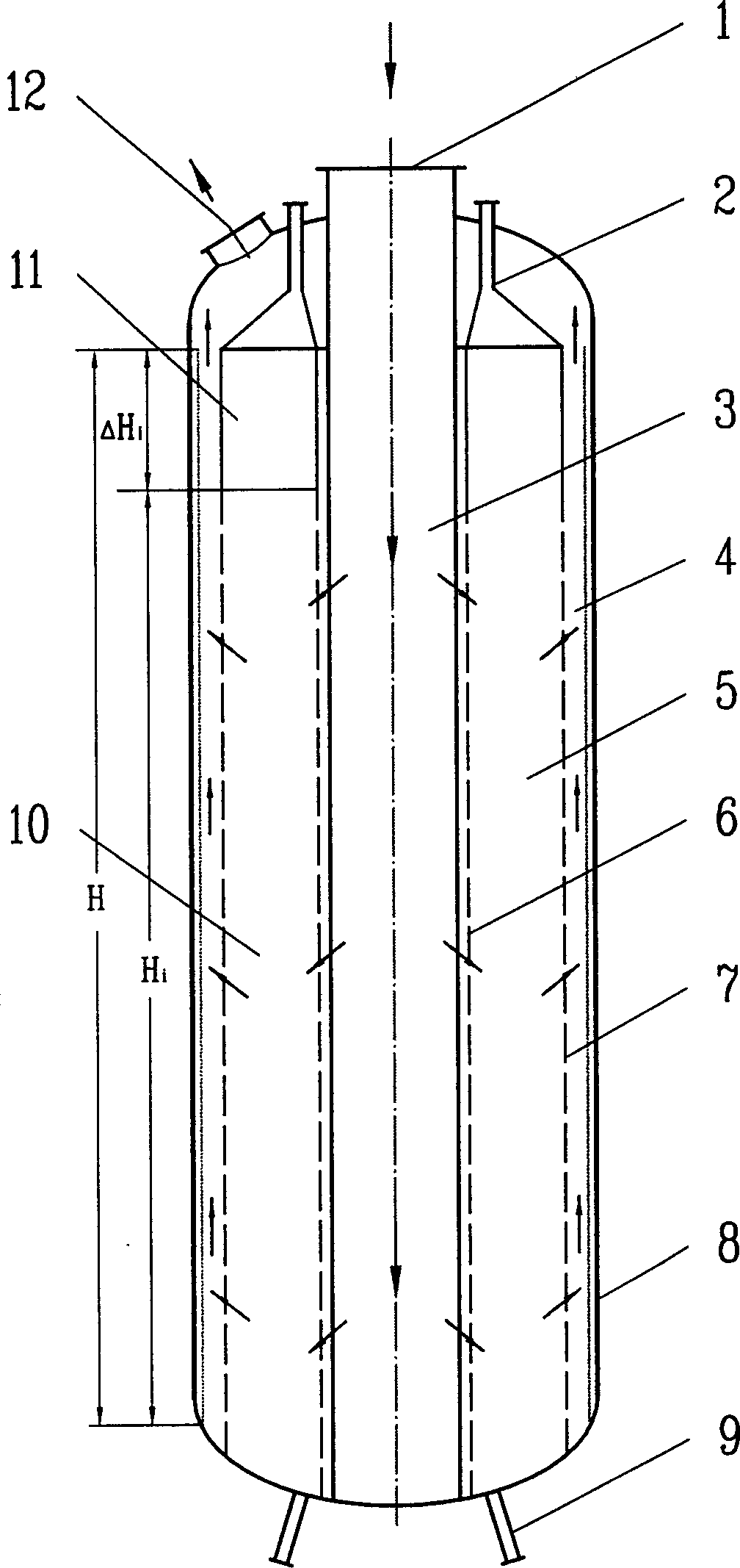
[0056] figure 1 The described reactor works like this:

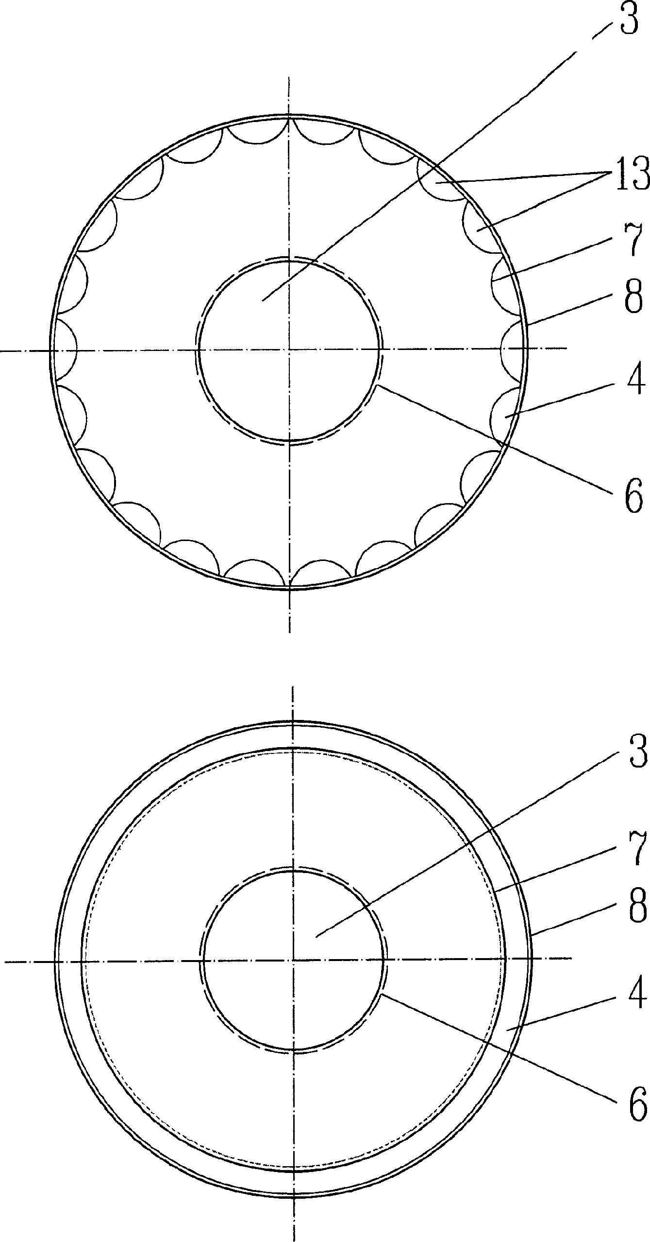
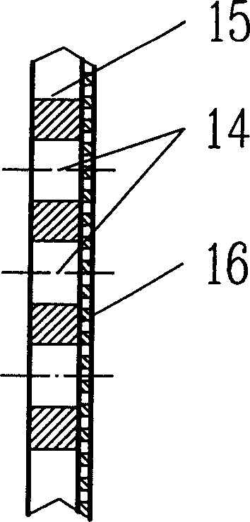
[0057] The molar ratio of hydrogen to hydrocarbon in the raw material is 1-3, the reaction temperature is 420-580°C, the reaction pressure is 0.2-0.8Mpa, and the weight space velocity is 0.5-2.5 hours -1 , the reaction material enters the split flow channel 3 formed by the inner porous wall cylinder 6 from the reaction material inlet 1, flows radially into the radial bed region 10 through the inner distribution holes 14 on the inner porous wall cylinder 6, and then passes through the outer porous wall from the inside to the outside The distribution hole 14 on the wall 7 or the distribution hole 19 through the porous hollow element 13 enters the reaction product collecting channel 4 for centrifugal flow, and the reactant material flows in the opposite direction in the split flow channel 3 and the collecting flow channel 4, and the catalyst After the particles flow into the catalyst bed 5 from the catalyst feed pipe 2, th...


PUM

PropertyMeasurementUnit
porosityaaaaaaaaaa
porosityaaaaaaaaaa
porosityaaaaaaaaaa

Abstract

The present invention discloses a reaction method applicable to continuous catalytic reformation and its reaction equipment. Said method adopts a circular pressure container with catalytic bed as raction equipment, the gas inlet and gas outlet are positioned on same end of said reaction equipment, said catalytic bed is formed from external porous wall and circular internal porous wall cylinder in which the catalytic is filled. Said catalyst can be continuously flowed from top to bottom by means of gravity, at the same time the reaction material can be flowed from top to bottom in distributary channel and can be flowed from bottom to top in the collecting channel, and can implement inverted U-type radial centrifugal flow from interior to exterior in the reaction equipment.

Description

technical field [0001] The invention relates to a reactor suitable for gas-solid phase catalytic reforming, paraffin catalytic dehydrogenation and catalytic dehydrogenation of substituted aromatic hydrocarbons. Background technique [0002] In the existing reaction methods for catalytic reforming, paraffin catalytic dehydrogenation and alkylaromatics catalytic dehydrogenation, gas-solid phase moving bed radial catalytic reactors are generally used. The gas-solid moving bed radial reactor is generally composed of an upper head, a cylindrical side wall and a bottom head to form the outer shell of the reactor. In the reactor, there is a cylindrical outer porous cylinder and a cylindrical outer shell. The annular space formed by the inner porous cylinder forms a cylindrical catalyst bed after the catalyst is loaded. The cylindrical inner porous cylinder can prevent catalyst particles from entering the inner space of the inner porous cylinder, and at the same time it can be used...

Claims


Application Information

Patent Timeline
Patent Type & Authority Patents(China)
IPC IPC(8): C10G69/08
Inventor 朱子彬朱学栋李瑞江俞丰吴勇强徐志刚张成芳
Owner EAST CHINA UNIV OF SCI & TECH
Why Eureka
Try Eureka