Catalytic reforming and catalytic dehydrogenation fixed bed radial reactor

A catalytic dehydrogenation and catalytic reforming technology, which is applied in catalytic cracking, chemical instruments and methods, cracking, etc., can solve the unsuitable requirements of catalytic reforming and catalytic dehydrogenation, and does not solve the problem of sparger control pressure drop, reactor Complicated internal structure and other issues to achieve the effects of avoiding heat loss, uniform axial temperature, and reducing pressure drop

Inactive Publication Date: 2005-12-21
EAST CHINA UNIV OF SCI & TECH
View PDF7 Cites 2 Cited by
  • Summary
  • Abstract
  • Description
  • Claims
  • Application Information

AI Technical Summary

Problems solved by technology

[0005] 2. U.S. Patent No. 3,099,208 believes that there is a dead zone locally in the catalyst seal. In order to avoid coking and improve the utilization rate of the catalyst there, it is proposed to use a cone structure for the catalyst seal, but this leads to an increase in the height of the catalyst seal. Complex structure
[0006] 3. The reactor adopts centripetal flow, and the reaction gas flows downward in the shunt channel between the side wall of the cylindrical container and the outer cylinder of the porous wall. Due to heat loss, the difference in the axial temperature of the bed will be caused, which will affect the heat absorption. particularly unfavorable reaction
[0007] 4. The centripetal flow from the outside to the inside does not meet the requirements of volume-enhancing reaction catalytic reforming and catalytic dehydrogenation along the molecular weight growth in the reaction process. Therefore, US Patent No. 5,885,442 adopts the centrifugal flow mode of reaction gas, which is beneficial to obtain Higher octane number gasoline and increased operating load, but did not solve the defect of large pressure drop due to Z-type flow distributor control

Method used


Image

  • Catalytic reforming and catalytic dehydrogenation fixed bed radial reactor
  • Catalytic reforming and catalytic dehydrogenation fixed bed radial reactor
  • Catalytic reforming and catalytic dehydrogenation fixed bed radial reactor

Examples


Embodiment 1

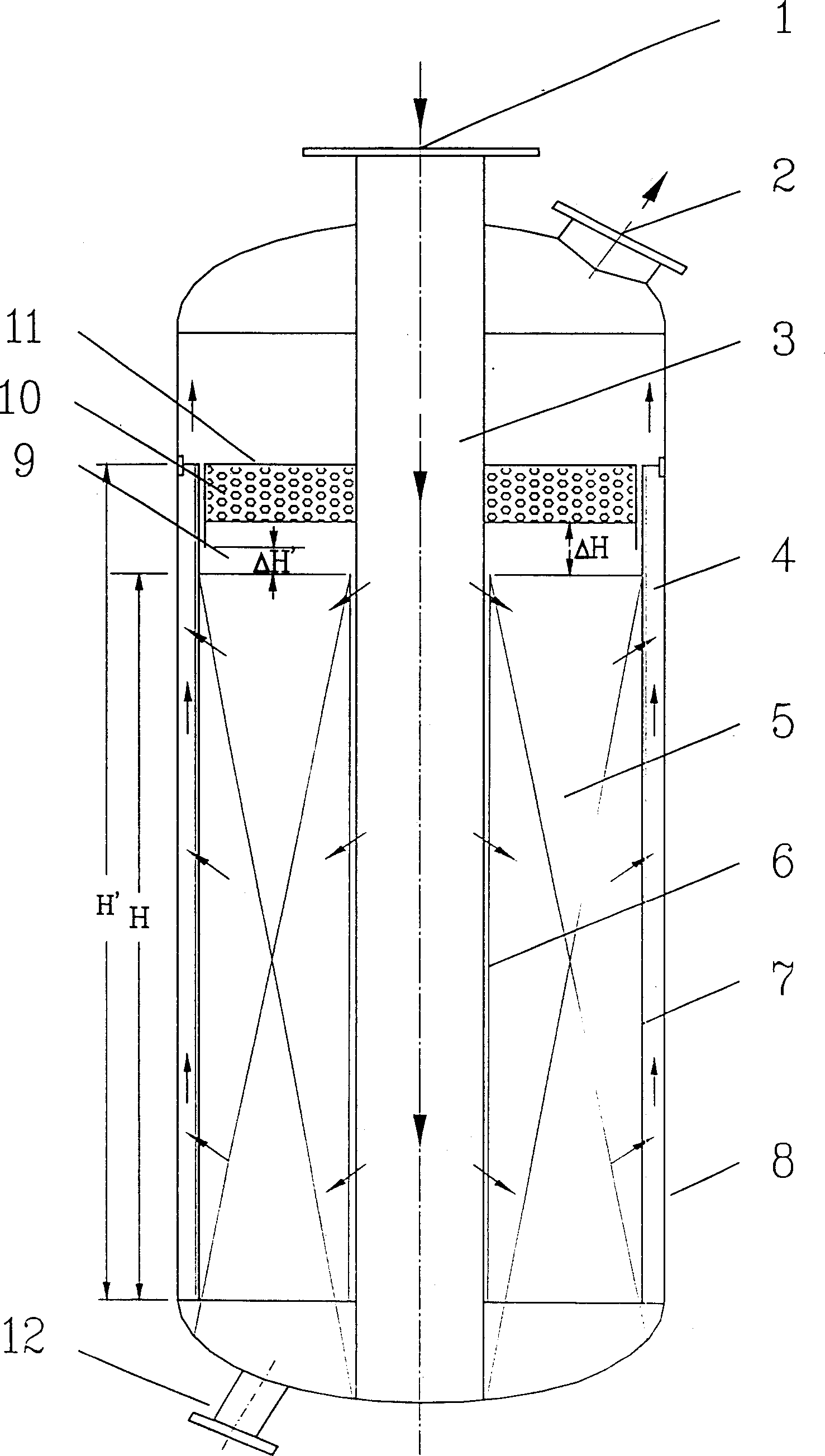
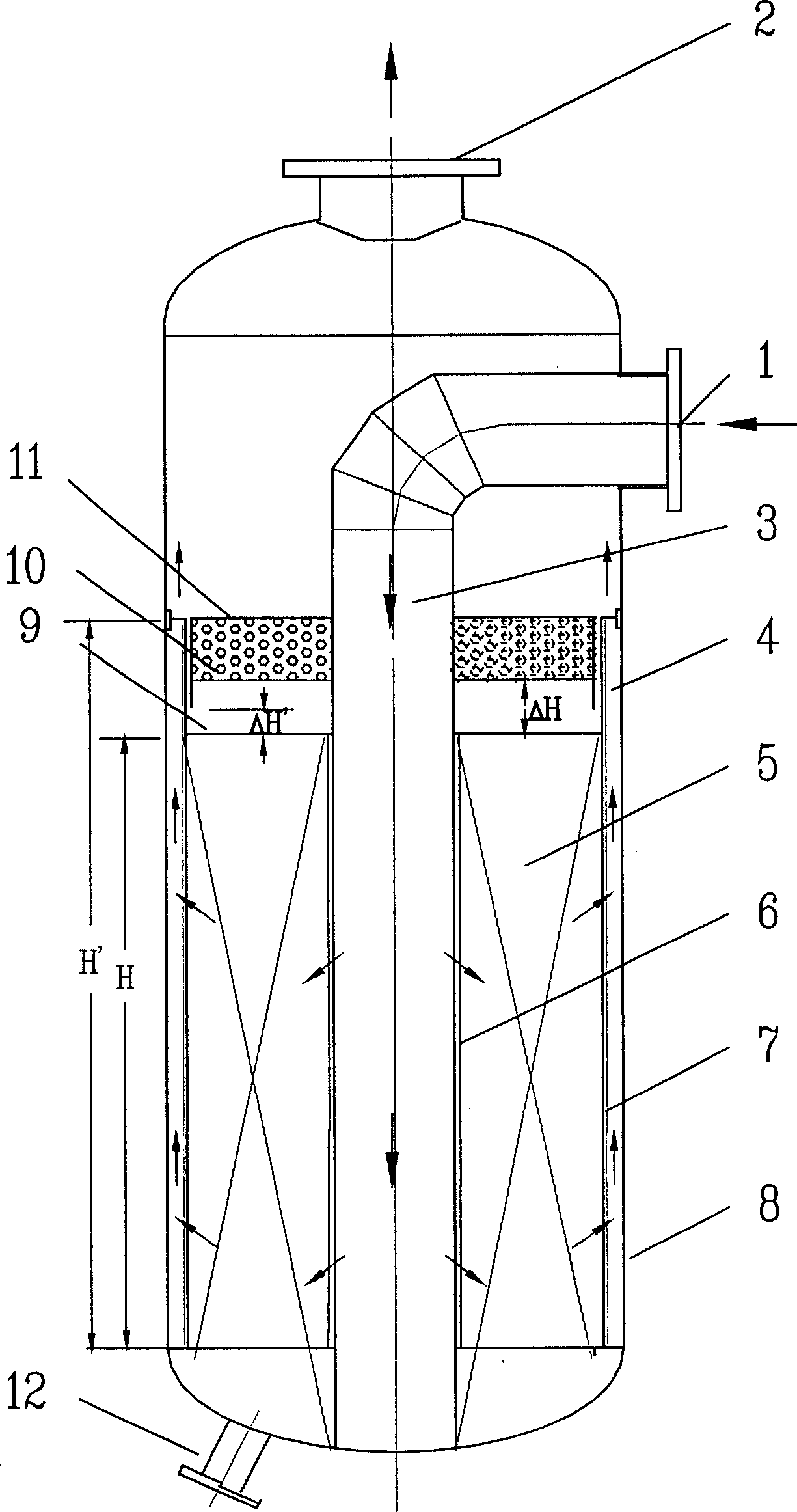
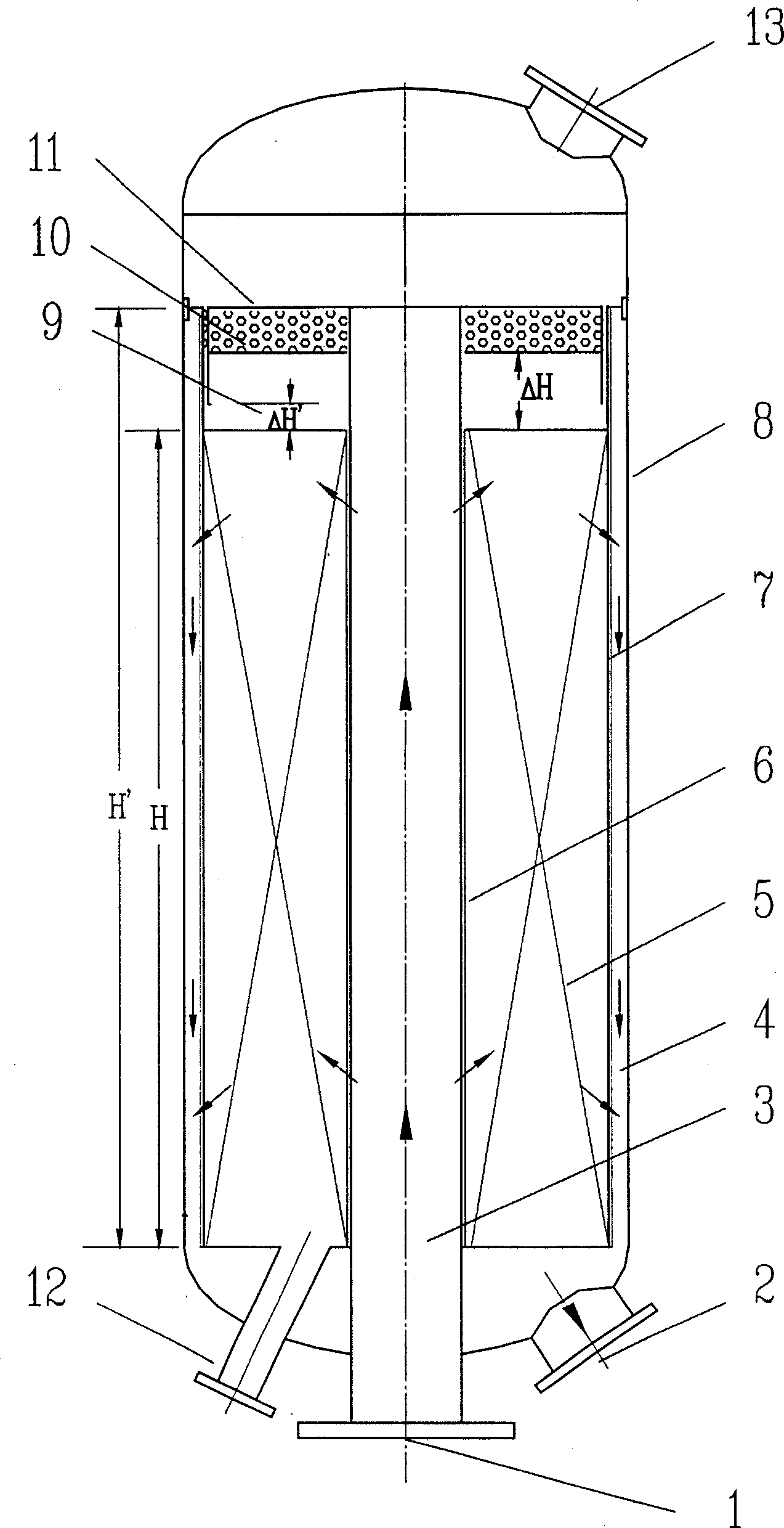
[0068] Example 1 The molar ratio of hydrogen to hydrocarbons in the raw material is 6-10, and the weight-to-liquid space velocity is 1.0-3.0h -1 , The semi-regenerative catalytic reforming reaction process with a reaction temperature of 450-550°C and a reaction pressure of 1.2-3.0MPa can be used figure 1 , figure 2 or image 3 Any one of the three ways shown.

Embodiment 2

[0069] Example 2 H in the raw material 2 The molar ratio of O / ethylbenzene is 8~10, and the liquid space velocity of ethylbenzene is 0.35~0.45h -1 , The ethylbenzene dehydrogenation reaction process with a reaction temperature of 550-645°C and a reaction pressure of 45-80Kpa (absolute pressure) can be used figure 1 , figure 2 or image 3 Any one of the shown reactors can be implemented.

[0070] The reaction gas enters the split flow channel 3 formed by the inner porous wall cylinder 6 from the reaction gas inlet 1, flows radially into the radial bed area 5 through the inner distribution holes 15 on the inner porous wall cylinder 6, and then passes through the outer porous wall from the inside to the outside. 7 enters the reaction gas collecting channel 4 for centrifugal flow, and the reaction gas flows in the opposite direction in the collecting channel 4 and the split channel 3, and then flows out through the outlet 2 of the reaction gas along the collecting channel.


PUM

PropertyMeasurementUnit
porosityaaaaaaaaaa
porosityaaaaaaaaaa
porosityaaaaaaaaaa

Abstract

The invention discloses a fixed-bed reactor for catalytic reforming and catalytic dehydrogenation. The reactor adopts a circular pressure vessel (8) with a catalytic bed (5), and the gas inlet (1) and outlet (2) are located at At the same end of the container (8), the catalytic bed (5) is composed of an outer porous wall (7) and a circular inner porous wall tube (6). The catalyst is filled in the middle, and there is a cover plate sealing structure above the catalyst. The circular inner porous wall The barrel (6) can adopt forms such as variable opening ratio or conical structure. The reaction gas flows centrifugally from the central inner porous cylinder to the porous outer cylinder in the reaction device, and the reaction gas flows in the opposite direction in the central inner cylinder and the porous outer cylinder, forming a centrifugal П-type radial reactor. This method has the characteristics of uniform distribution of reaction gas along the axial direction, pure radial flow in the catalyst bed, and small pressure drop through the reactor. The reactor is also suitable for other medium, low pressure or negative pressure gas-solid phase catalytic reactions.

Description

technical field [0001] The invention belongs to the technical field of hydrocarbon processing, and relates to a fixed bed gas-solid phase catalytic reaction device suitable for medium, low or negative pressure, in particular to a fixed bed radial reaction device suitable for catalytic reforming and catalytic dehydrogenation . Background technique [0002] For catalytic reforming and catalytic dehydrogenation, the reaction medium contains a large amount of hydrogen, and its hydrogen-to-hydrocarbon molar ratio is as high as 6-10 times or higher. A large number of gas cycles make reducing the pressure drop of the reactor an important factor for improving catalyst utilization and saving energy. the key to. In the existing reaction methods of catalytic reforming and catalytic dehydrogenation, in order to improve the utilization rate of the catalyst, the catalyst with small particle size is usually used; in order to reduce the pressure drop of the reactor and reduce the power con...

Claims


Application Information

Patent Timeline
Patent Type & Authority Patents(China)
IPC IPC(8): B01J8/02C10G11/10
Inventor 朱子彬朱学栋李瑞江俞丰陈允华吴勇强倪燕慧徐志刚张成芳
Owner EAST CHINA UNIV OF SCI & TECH
Why Eureka
Try Eureka