Timing switch

A timing switch, switch technology, applied in the direction of time program switch, electric switch, generating time signal at a predetermined time, etc.

Inactive Publication Date: 2005-05-25
MATSUSHITA ELECTRIC WORKS LTD +1
View PDF0 Cites 0 Cited by
  • Summary
  • Abstract
  • Description
  • Claims
  • Application Information

AI Technical Summary

Problems solved by technology

[0005] Therefore, the timing switch in the pr

Method used


Image

  • Timing switch
  • Timing switch
  • Timing switch

Examples


no. 1 example

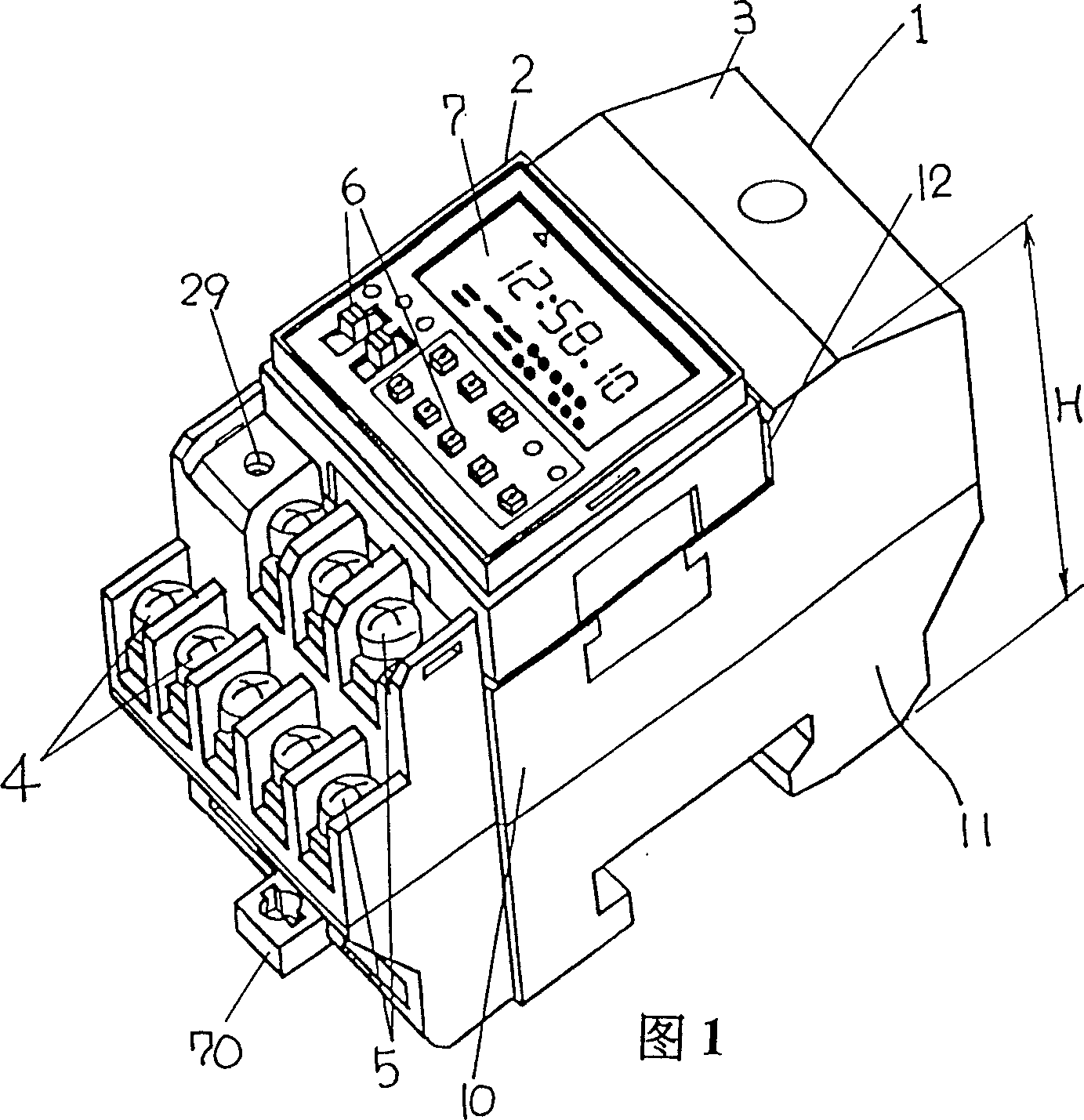
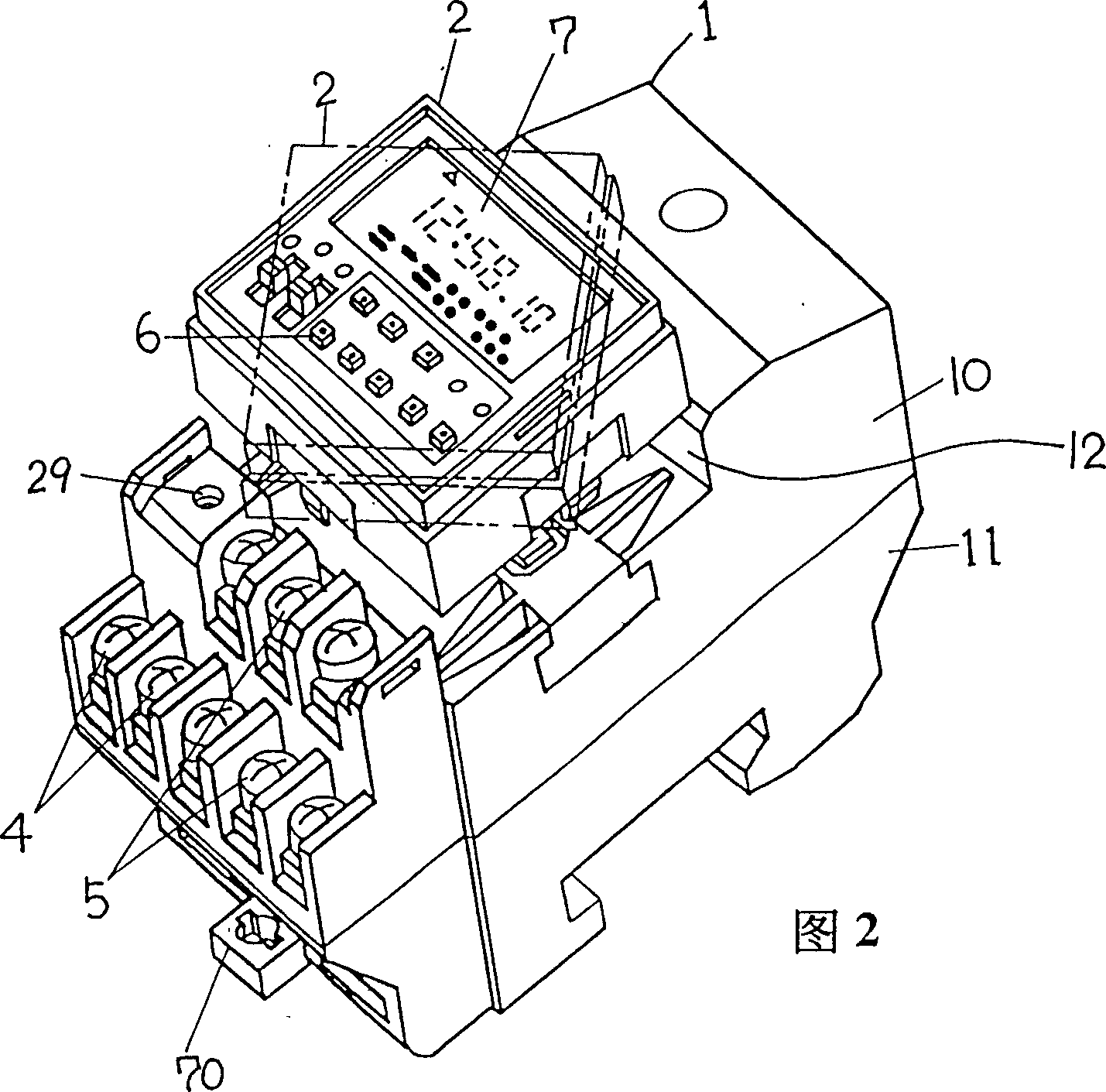
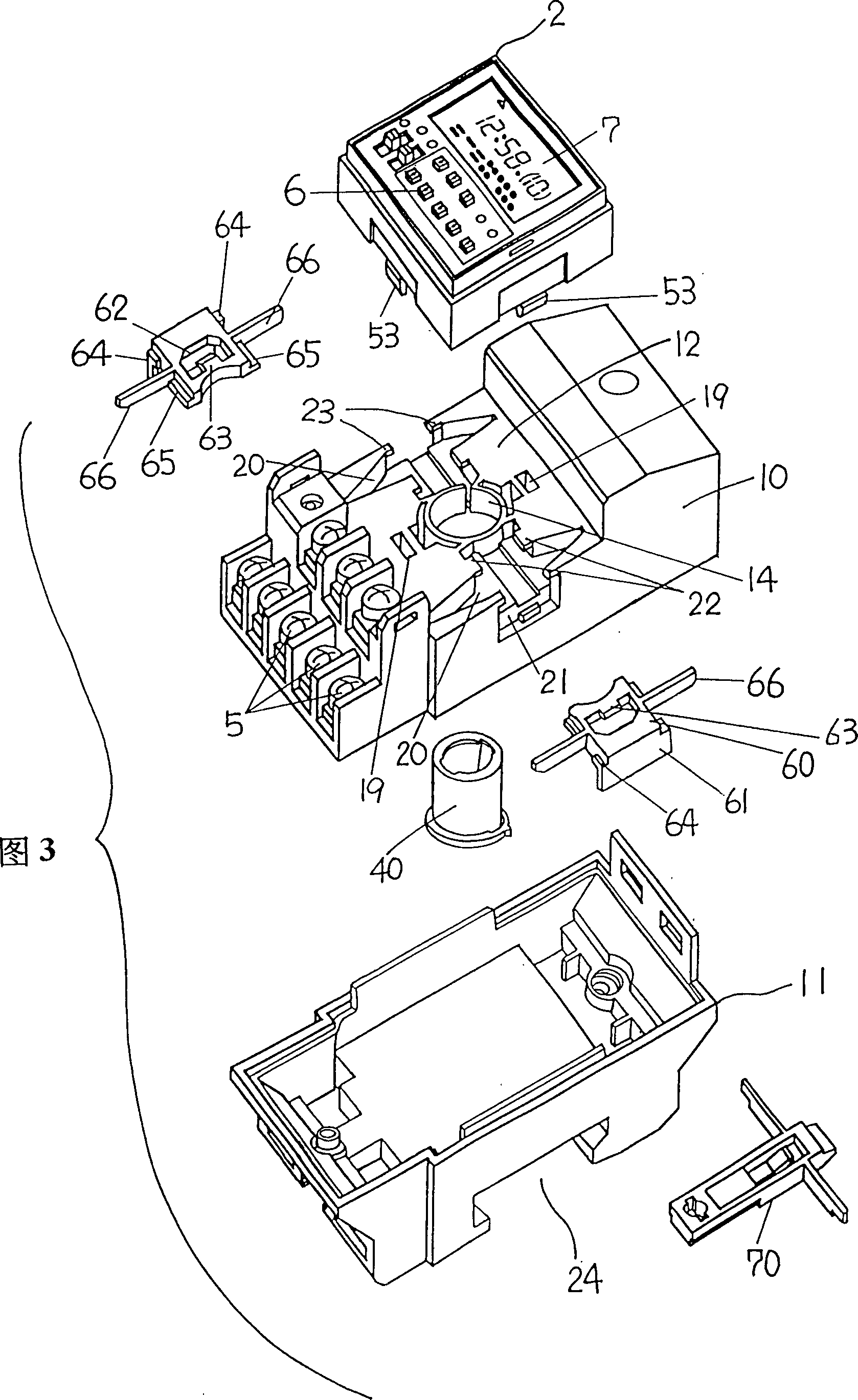
[0038]A timer switch 1 for turning on and off electrical equipment such as lighting at a set time, comprising a timer body 2 with an electrical timer built in, and an input terminal 4 with an electrical connection for a power supply and an electrical The output terminal 5 of the device is electrically connected to the switch body. The timer body 2 has a substantially square top surface, on which an input button 6 for inputting a set time into the electric timer and a display 7 for displaying the set time are arranged. The width of the switch body 3 is substantially equal to one side of the timer body 2 . If desired, the input and output terminals (4, 5) can be protected from the outside by an end cap (not shown). Reference numeral 29 represents the screw hole that end cover and switch body 3 are fixed. The switch body 3 is made of an electrically insulating material such as synthetic resin, and a switch part (not shown) is housed therein, and the switch part turns the electr...

no. 2 example

[0045] In the second embodiment, the timer switch 1C for turning on and off the electrical equipment at a set time includes a timer body 2C and a switch body 3C. The timer body is equipped with an electric timer, and the switch body has an input end 4C electrically connected to the power supply and an output end 5C electrically connected to the electrical equipment. The timer body 2C has a substantially square top surface, on which an input button 6C for inputting a set time into the electric timer and a display 7C for displaying the set time are arranged. The width of the switch body 3C is approximately equal to one side of the timer body 2C. The switch body 3C houses a switch part (not shown) for turning on and off the electrical equipment with the power supply according to the output of the electronic timer. A groove 12C is formed in the top surface of the switch body 3C. The timer body 2C is movable between a normal position and an extended position. where the usual loc...


PUM


Abstract

A time switch for starting and stopping an electric appliance at set times comprises an electric timer, a display housing a display for the set times, and a switch housing having a concave. The switch housing has input terminals, output terminals, and a switch unit for connecting and disconnecting the electric appliance to and from an power source in accordance with an output from the timer. The time switch includes a coupling member for connection of the display housing to the switch housing. The coupling member comprises a cylinder through which lead wires extends between the timer and the switch unit. The coupling member is movably supported to the switch housing along a center axis of the cylinder so that the display housing can move between a normal position where the display housing fits within the concave and an extended position where the display housing projects out of the concave. The coupling member is rotatably supported to the switch housing such that the display housing can rotate about the center axis of the cylinder at the extended position. This time switch presents an advantage that it is easy to check the set times on the display irrespective of installation angle of the time switch to a switchboard or the like.

Description

technical field [0001] The present invention relates to a timer switch for activating and deactivating a piece of electrical equipment at set times. Background technique [0002] In the past, an electronic timer switch for checking the time based on a clock signal generated by a quartz oscillator at a fixed cycle has been known. This kind of timing switch usually includes a timer body that combines a quartz oscillator with an electrical timer, and has an input terminal that is electrically connected to a power supply, an output terminal that is electrically connected to an electrical device, and an electrical timer. A switch body that outputs a switch component that connects electrical equipment to and from the power supply. The display body is formed on its surface by an input button for inputting the set time into the electric timer and a liquid crystal display displaying the set time. This kind of timing switch can be installed on the switchboard to control the switchin...

Claims


Application Information

Patent Timeline
IPC IPC(8): G04G15/00H01H9/18H01H43/02
CPCG04G15/00H01H9/181H01H43/022
Inventor 室井裕明松田正则高桥久雄柳田一男
Owner MATSUSHITA ELECTRIC WORKS LTD
Why Eureka
Try Eureka