Floor covering plate

A technology of ground covering and floor plates, applied in the direction of floors, dovetail connections, circuits, etc., can solve problems such as low bending resistance

Inactive Publication Date: 2005-07-20
WINDMOLLER FLOORING PROD
View PDF6 Cites 0 Cited by
  • Summary
  • Abstract
  • Description
  • Claims
  • Application Information

AI Technical Summary

Problems solved by technology

This lower flex resistance is of course unacceptable in today's environment as the currently preferred method of bond laying

Method used


Image

  • Floor covering plate
  • Floor covering plate
  • Floor covering plate

Examples


Embodiment Construction

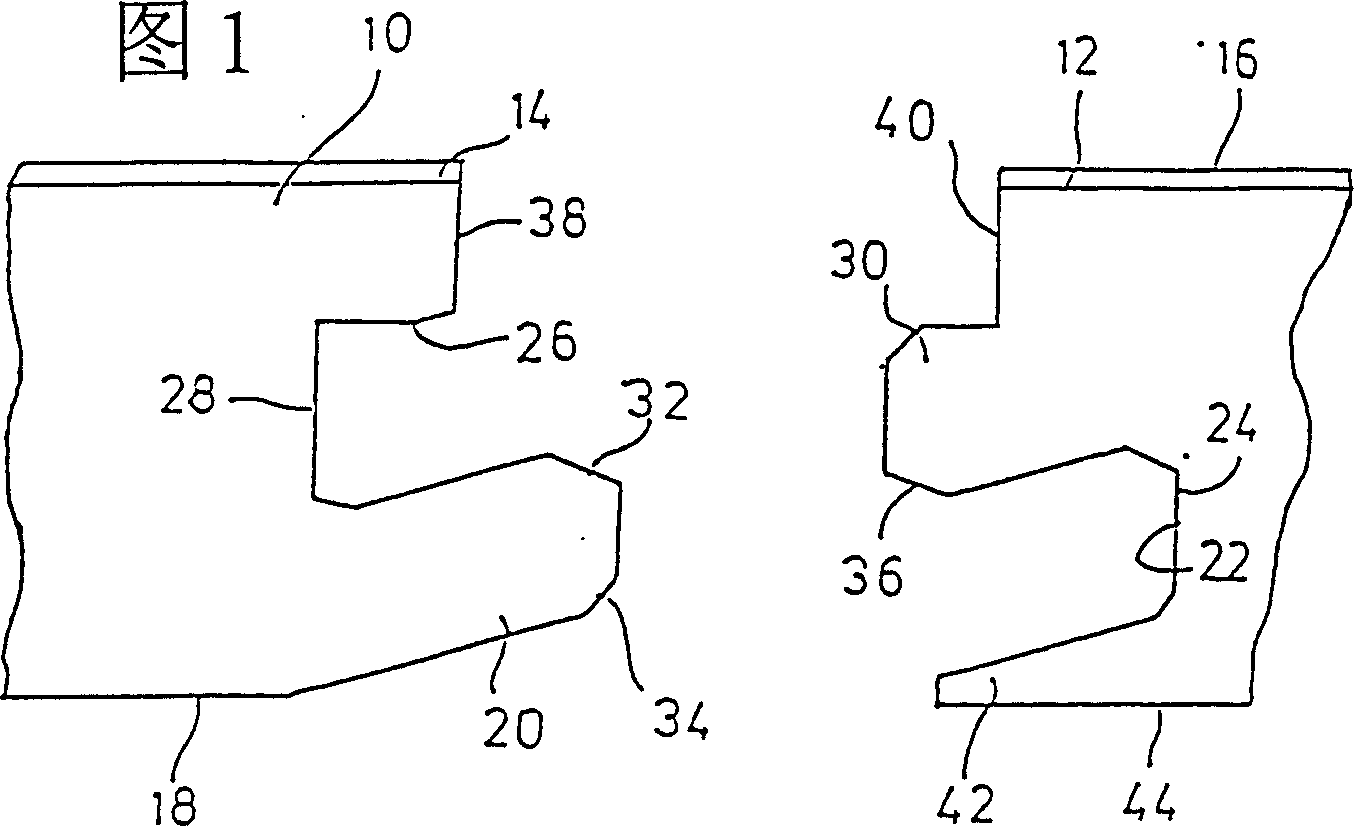
[0033] FIG. 1 shows the edges of two floorboards to be joined, of which the left-hand one will be referred to below as the first floorboard 10 and the right-hand one as the second floorboard 12 . The floorboards 10 and 12 may be made of laminate, ie of derived wood products and / or plastic, or of compacted wood. The top cover layers 14, 16 are represented here by way of example. The first floorboard 10, shown on the left in FIG. The inside of the groove 22, ie towards the rear end 24 of the groove, is at the same angle as the tongue 20 protrudes upwards.

[0034]Arranged above the obliquely raised tongue 20 in the first floorboard is a groove 26 , the bottom wall of which is formed by the top surface of the tongue 20 sloping down towards the groove rear end 28 . Instead, the top wall of the groove 26 extends substantially horizontally, which is parallel to the floor plane of the two floorboards 10 , 12 .

[0035] The top of the groove 22 in the second floorboard 12 is define...


PUM


Abstract

The invention relates to a floor covering plate, especially a laminated panel, wooden flooring element or the like, comprising an edge profile section on at least two opposite-lying edges in the form of a modified groove and tongue assembly which is used to connect adjacent plates, a further arrangement respectively consisting of a groove (22, 122, 26, 126) and a tongue (20, 120, 30, 130) on the at least two edges, whereby the tongue on one edge of the first plate ascends at a slanted angle and the groove on an associated edge of a second plate ascends at a slanted angle from the lower part of the plate. The edge profile sections are directly incorporated into the support material of the floor covering plate, the groove (26, 126) of the first plate being located directly above the tongue associated therewith (20, 120) and the lower wall of the groove descending towards the bottom of the groove (28, 128) as the tongue (20, 120) of the first plate ascends. The upper wall of the groove (26, 126) of the first plate (10, 110) extends in a substantially parallel manner in relation to the plane of the plate and the tongue (30, 130) of the second plate (12, 112) is provided with an upper surface lying substantially parallel to the plane of the plate, whereby a lower surface extends downwards as far as the end of the tongue (30, 130), corresponding to the shape of the groove (26, 126).

Description

technical field [0001] The present invention relates to a floor covering board, in particular to laminated strips, parquet elements, veneered floor elements, ready-to-install parquet elements etc., in at least two modified An edge profile on the opposite side of the groove and tongue joint form, a conforming construction consisting of a groove and a tongue on each of at least two sides, wherein the tongue on one side of the first floorboard The groove on the side associated with the second floorboard rises sloping upwards from the bottom of the floorboard. Background technique [0002] A floor covering panel of this type is disclosed in DE3343604C2. In this prior art floorboards, the act of joining two identical floor covering panels results in an "improved" groove and tongue joint, in which the Joining so that adjacent floorboards remain in place, i.e. they cannot be unintentionally separated. Although this level fixation can be achieved by bonding adjacent floorboards t...

Claims


Application Information

Patent Timeline
Patent Type & Authority Patents(China)
IPC IPC(8): E04F15/02E04F15/04
CPCE04F15/04E04F2201/0115E04F15/02E04F2201/07Y10T403/7073Y10T403/7045E04F2201/0153Y10T403/7094E04F2201/025E04F2201/027F16B2200/30
Inventor B·斯耐德
Owner WINDMOLLER FLOORING PROD
Why Eureka
Try Eureka