Method and apparatus for precision alignment and tack welding of weld-neck pipe fittings to pipe

a technology of weld-neck pipe fittings and aligning devices, which is applied in the direction of soldering devices, manufacturing tools,auxillary welding devices, etc., can solve the problems of difficult positioning and positioning of fittings accurately relative to pipes, inability to establish precision sealing with respect to the sealing flange of adjacent pipe members, and heavy and expensive sets. , to achieve the effect of simple and efficient positioning

Inactive Publication Date: 2019-05-28
BRANTLEY RICHARD
View PDF49 Cites 0 Cited by
  • Summary
  • Abstract
  • Description
  • Claims
  • Application Information

AI Technical Summary

Benefits of technology

[0006]It is a principal feature of the present invention to provide a novel method and apparatus for simple and efficient positioning of a weld-neck pipe flange fitting relative to the beveled end of a pipe to which it is to be welded.
[0008]It is a further feature of the present invention to provide a novel method and apparatus for positioning and weld mounting a pipe fitting, such as a pipe flange fitting to an end of a section of pipe by using a pair of relatively moveable alignment components that are expanded within the pipe and pipe flange fitting by relatively moveable tapered surfaces, causing edges or surfaces thereof to establish aligning and gripping contact with the cylindrical internal surfaces of a section of pipe and with a weld-neck pipe fitting. The weld-neck pipe fitting may be a pipe flange fitting or any other type of pipe fitting having a cylindrical flow passage and a weld prepared cylindrical tube or spool that is intended for positioning in slightly spaced linear alignment with the weld prepared end of a pipe.
[0010]It is another feature of this invention to provide an apparatus and process for aligning a weld-neck flanged pipe fitting for weld connection with a pipe and ensuring precision location of the bolt holes of the connection flange of the fitting to permit ease of bolted connection of the sealing flange of the fitting with the sealing flange of an adjacent pipe.
[0012]The two wedge-shaped members are positioned in loosely assembled relation with the pipe and the weld-neck fitting and the weld-neck fitting is then positioned in closely spaced relation with the beveled end of the pipe. For establishing lateral internal clamping movement of the assembled wedge-shaped members within the cylindrical surfaces to provide clamping or gripping activity, one of the wedge-shaped members is maintained substantially static while the other of the wedge-shaped members is moved linearly within the cylindrical surfaces of the pipe and fitting. Upon relative linear movement of the wedge-shaped members, inclined reactive geometry of each of the wedge-shaped members causes lateral expansion of the assembled wedge members, driving the spaced parallel corners of the wedge members with sufficient force to establish internal clamping thereof within the pipe and fitting thus securing the weld-neck fitting in a selected precision position relative to the end of the pipe to which the fitting is to be welded. Relative movement of the wedge-shaped members within the pipe and fitting causes centering alignment of the weld-neck fitting relative to the flow passage of the pipe, thus positioning the circular end of the tubular weld connection spool of the fitting in precisely aligned relation with the circular beveled end of the pipe.
[0015]When weld-neck pipe fittings incorporate a connection and sealing flange it is often necessary to ensure that the bolt holes of the flange are properly oriented for alignment with the bolt holes of the connection and sealing flange of a pipe to which the pipe fitting is designed to be connected. Typically, when a weld-neck flange fitting is being aligned and supported in relation to the pipe to which it will be welded, two adjacent bolt holes of the connection and sealing flange are aligned horizontally. A tool, not forming a part of the present invention, is commercially available that has a tool body providing support for two spaced hole engaging members that each have conical surfaces for engagement within two of the bolt holes of the connection and sealing flange. With these bolt hole engaging devices in place, a level device can engage the hole engaging members and confirm precise horizontal positioning of the two bolt holes. Prior to installing the tack welds, the flanged fitting can be rotated as necessary to ensure precise horizontal positioning of the two bolt holes of the flange, thereby confirming that the bolt holes of the flange will match the positions of the bolt hole of the connection and sealing flange of a pipe to which the flange of the fitting will be connected. The internal clamping wedge assembly of the present invention is efficiently used for alignment and internal clamping of a weld-neck flange fitting in the manner discussed in detail above, while also employing a bolt hole alignment tool to achieve and confirm precise horizontal orientation of two adjacent bolt holes of the connection and sealing flange of the fitting.

Problems solved by technology

Since a weld-neck flange fitting is typically of short length, it is often quite difficult to position it accurately relative to the pipe and to secure it immovably to the pipe, especially when the positioning and welding work is done during field conditions.
If the tack welded flange fitting is determined to have been inaccurately positioned following installation of the tack-welds, the sealing flange of the fitting will not be capable of establishing precision sealing with respect to the sealing flange of an adjacent pipe member.
When weld-neck flange fittings are welded in commercial welding shop conditions, for the most part heavy and expensive set-up machinery is used to establish accurate positioning of weld-neck flange fittings relative to pipe.
In small shop conditions and field conditions precision set-up of weld-neck flange fittings and some other pipe fittings can be a matter of trial and error.
Though pipe flange weld-neck fittings have been welded to pipes for many years, it has long been determined that it is exceedingly difficult to establish stable precision positioning of a pipe flange fitting to a section of pipe so that the pipe flange fitting is oriented with its flange face precisely perpendicular to the external cylindrical surfaces of both the pipe and the tubular section of the pipe flange fitting and thus perpendicular with the longitudinal axes of the flow passages of the pipe and the pipe flange fitting.

Method used


Image

  • Method and apparatus for precision alignment and tack welding of weld-neck pipe fittings to pipe
  • Method and apparatus for precision alignment and tack welding of weld-neck pipe fittings to pipe
  • Method and apparatus for precision alignment and tack welding of weld-neck pipe fittings to pipe

Examples


Embodiment Construction

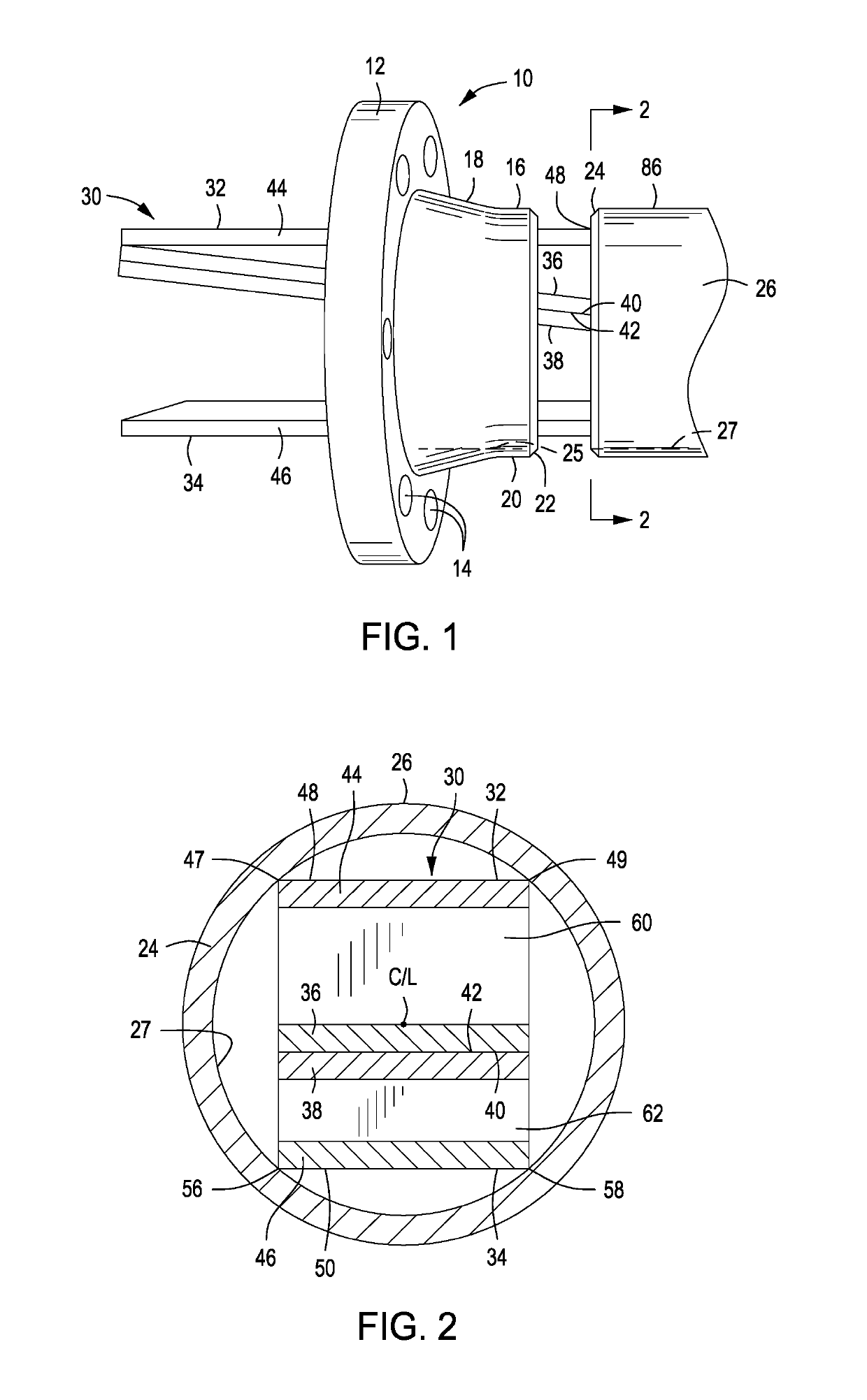
[0027]Referring now to the drawings and first to FIG. 1, a sealing flange type weld-neck pipe fitting for a welded connection to a pipe is shown generally at 10 and has a sealing flange member 12 having an array of bolt holes 14 that receive threaded bolts or studs for securing the sealing flange member in tightly sealed relation with an identical sealing flange member of a fluid or gas handling piping system. The pipe fitting has a tubular weld connection spool 16 extending from one side of the sealing flange and being designed for optimum strength to accommodate piping loads. The weld connection spool 16 has a tapered connection section 18 projecting from the sealing flange member 12 and merging with a generally cylindrical connection section 20 typically having a circular beveled weld preparation.

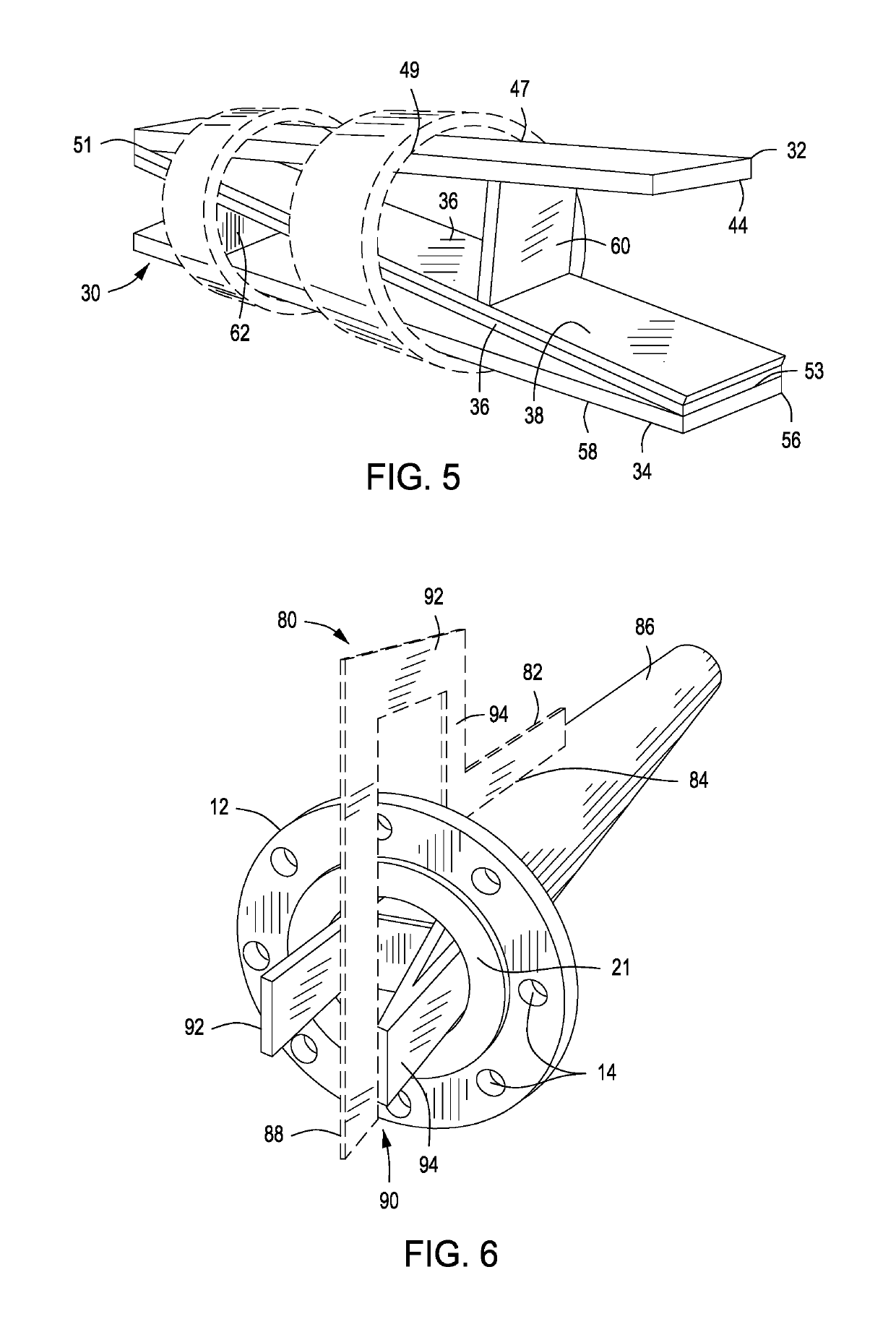
[0028]The sealing flange 12 defines a circular planar sealing face 21, shown in FIG. 6, that establishes sealing engagement with an identical sealing flange of a pipe as the sealing flan...


PUM

PropertyMeasurementUnit
dimensionaaaaaaaaaa
lengthaaaaaaaaaa
forceaaaaaaaaaa

Abstract

Internal clamping of a weld-neck fitting to a pipe in preparation for precision tack welding of the fitting to the pipe is established by a pair of alignment and clamping wedge members, each having alignment and gripping members and angulated reaction surfaces which are positioned within the pipe and weld-neck fitting with the angulated reaction surfaces in relatively moveable engagement. One of the alignment and clamping wedge members is moved linearly, causing the angulated reaction surfaces to translate the linear movement to lateral movement, forcing the alignment and gripping members laterally against the internal surfaces of the pipe and fitting and supporting the fitting in precision aligned relation with the pipe to facilitate tack welding. A gauge member confirms precision alignment of the fitting with the pipe before and after applying the tack welds, then the alignment and clamping apparatus is loosened by opposite linear movement of the wedge members which are removed to permit final weld connection of the fitting to the pipe.

Description

BACKGROUND OF THE INVENTIONField of the Invention[0001]The present invention relates generally to a method and apparatus for aligned positioning of weld-neck pipe fittings, such as pipe flange fittings relative to the beveled end of pipe to permit tack-welding of the fittings to secure the fittings in immoveable relation with the pipe to permit finish welding. More particularly, this invention concerns the use of an alignment method and system that establishes precision alignment of a pipe flange fitting to a pipe, confirming precision pipe flange alignment before and after tack welding the fitting to the pipe. This invention also permits simple and efficient precision spacing of the tubular beveled end of a weld-neck pipe fitting with the beveled end of a pipe and permits verification of precise perpendicular orientation of the sealing flange of a weld-neck pipe flange fitting with respect to the external cylindrical surface and longitudinal center-line of the pipe by means of a po...

Claims


Application Information

Patent Timeline
Patent Type & Authority Patents(United States)
IPC IPC(8): B23K37/04F16L23/026B23K37/053B23K101/06
CPCB23K37/0536F16L23/026B23K37/0531B23K2101/06
Inventor BRANTLEY, RICHARD
Owner BRANTLEY RICHARD
Why Eureka
Try Eureka