Power Tool

Active Publication Date: 2011-07-14
HITACHI KOKI CO LTD
View PDF14 Cites 104 Cited by
  • Summary
  • Abstract
  • Description
  • Claims
  • Application Information

AI Technical Summary

Benefits of technology

[0090]With this structure, the disc grinder can be easily assembled, since the sensor associated with the brushless motor is

Problems solved by technology

If a plurality of power tools each having a brushless motor are connected to an identical external power source, each power source box is moved in accordance with the movement of the user, so that power source boxes are bumped against one another other causing damage to the power source boxes.
However, the layout of the motor driver circuit as described in these JP publications provides dr

Method used


Image

  • Power Tool
  • Power Tool
  • Power Tool

Examples


first embodiment

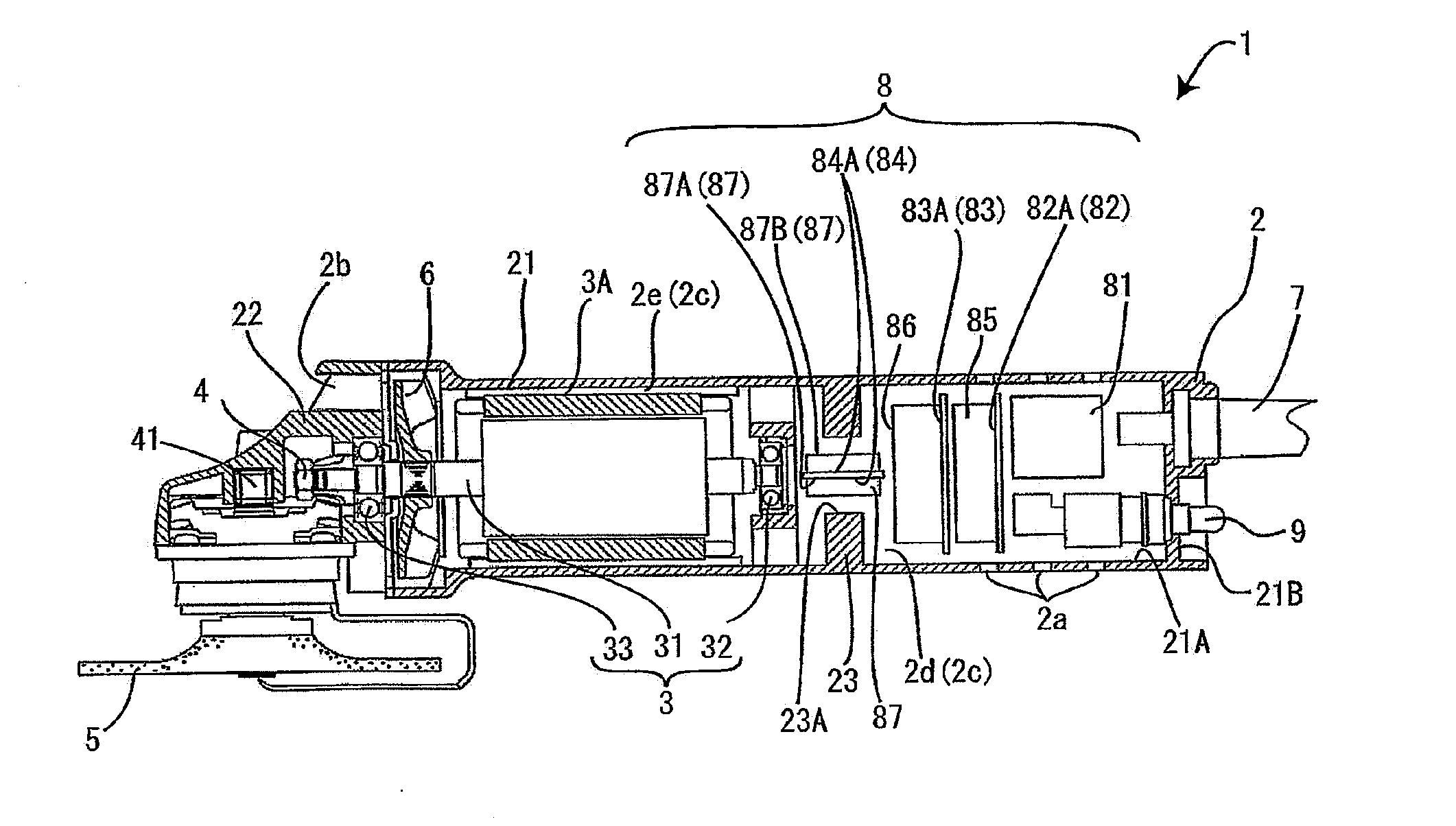
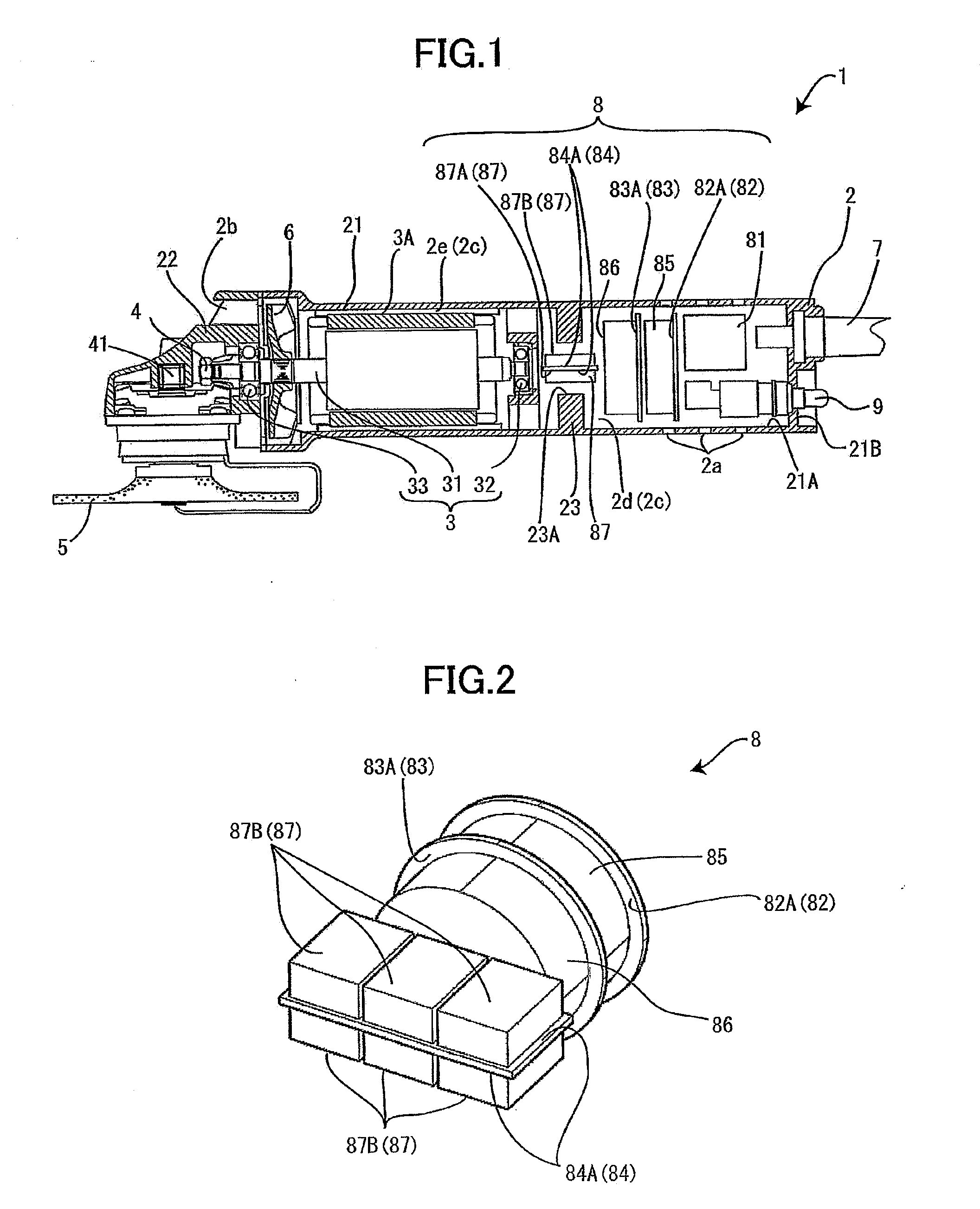
[0189]A disc grinder as a power tool according to the present invention will be described with reference to FIGS. 1 and 2. The disc grinder 1 generally includes a housing 2, a motor 3 accommodated in the housing 2, a gear portion 4 rotationally driven by the motor 3, a grinding stone 5 rotated by the gear portion 4, a fan 6, and a power cord 7. In the following description, the grinding stone side and the power cord side will be referred to as a front side and a rear side, respectively.

[0190]The housing 2 includes a grip portion 21 and a gear cover 22. The grip portion 21 accommodates therein the motor 3, the fan 6 and a motor driver circuit 8 controlling the motor 3. The grip portion 21 has a generally cylindrical shape and is constituted by a pair of complementary semi-cylindrical halves coupled to each other. In the grip portion 21, the motor 3, and the motor driver circuit 8 are fixed. The grip portion 21 has a rear portion formed with an air inlet port 2a for introducing an ext...

sixth embodiment

[0227]However, a disc grinder 501 has a housing including a motor housing 502 accommodating therein a brushless DC motor 506, a gear cover 503, and a tail cover 504 positioned at a front side and a rear side of the motor housing 502, respectively. The motor housing 502 has a grip portion (thinner portion) 502A having a size smaller than that of the gear cover 503 and the tail cover 504, the size being one of a diameter, a height and a width. The motor housing 502 has a fat portion at a front side of the thinner portion 502A. In the fat portion, a fan accommodating space is provided for accommodating therein a cooling fan 519. The motor housing 502 is integrally molded product made from a polymer resin such as polycarbonate. The fat portion has a radially outer portion formed with thread holes (not shown) extending in frontward / rearward direction.

[0228]The gear cover 503 is fixed to the fat portion by a plurality of screws 528 threadingly engaged with the thread holes of the fat por...


PUM


Abstract

An electric power tool includes a housing, a brushless motor, an output shaft, and a motor driver circuit. The housing defines an axial direction. The brushless motor is accommodated in the housing and having a drive shaft. The output shaft extends in a direction generally perpendicular to the drive shaft. The motor driver circuit is accommodated in the housing for driving the brushless motor. The housing has a cylindrical shape and has a part functioning as a grip portion.

Description

TECHNICAL FIELD[0001]The present invention relates to a power tool having a brushless motor.BACKGROUND ART[0002]A brushless motor exhibiting high efficiency can be used as a drive source for a power tool. However, the brushless motor requires a motor driver circuit which is not required in case of an ordinary motor having a brush. In case of a power tool having a brushless motor, the motor driver circuit is accommodated in a power source box additionally provided between a housing of a power tool and an external power source as shown in FIG. 1 of publication No. 2008-504136 which is a published Japanese translation of a PTC text. If a plurality of power tools each having a brushless motor are connected to an identical external power source, each power source box is moved in accordance with the movement of the user, so that power source boxes are bumped against one another other causing damage to the power source boxes.[0003]To avoid this problem, Japanese Patent Application publicat...

Claims


Application Information

Patent Timeline
IPC IPC(8): B24B23/02B24B47/12H02K7/14
CPCB24B23/028B24B47/12B25F5/02H02K11/0073H02K5/20H02K7/145H02K1/185H02K11/33B25F5/008H02K5/207
Inventor TANIMOTO, HIDEYUKITAKANO, NOBUHIROHOSOKAWA, NOBUHITO
Owner HITACHI KOKI CO LTD
Why Eureka
Try Eureka