Position adjustable load support mechanism

a technology of load support and position adjustment, which is applied in the direction of machine supports, building scaffolds, other domestic objects, etc., can solve the problems of limiting the materials available for the heavily stressed components, and difficulty in adjusting the counterbalancing for

Inactive Publication Date: 2005-02-22
CONNER JOHN P +1
View PDF15 Cites 125 Cited by
  • Summary
  • Abstract
  • Description
  • Claims
  • Application Information

AI Technical Summary

Benefits of technology

Accordingly, my load support mechanism provides several advantages over the prior art. Included in these advantages is the mounting position of the arm pivot axis, which is located some distance above the use

Problems solved by technology

This design has the inherent problem of requiring high counterbalancing forces from the gas spring, which in turn creates

Method used


Image

  • Position adjustable load support mechanism
  • Position adjustable load support mechanism
  • Position adjustable load support mechanism

Examples


Embodiment Construction

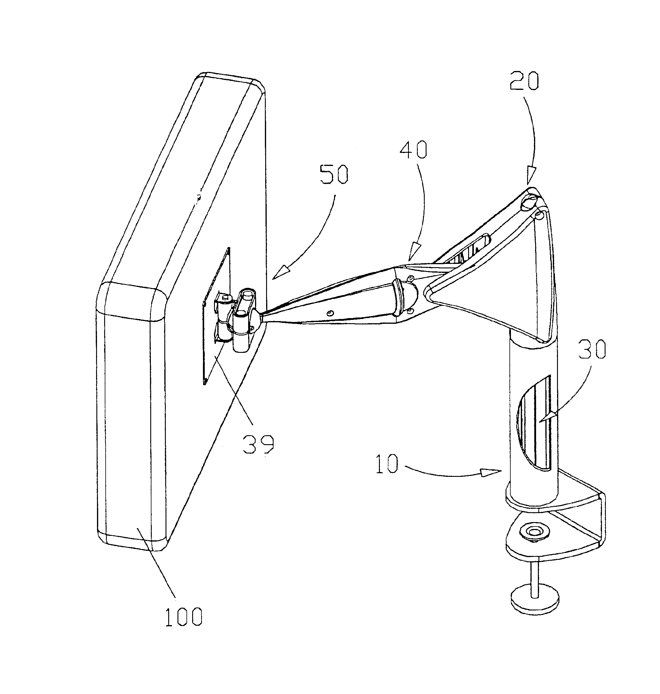
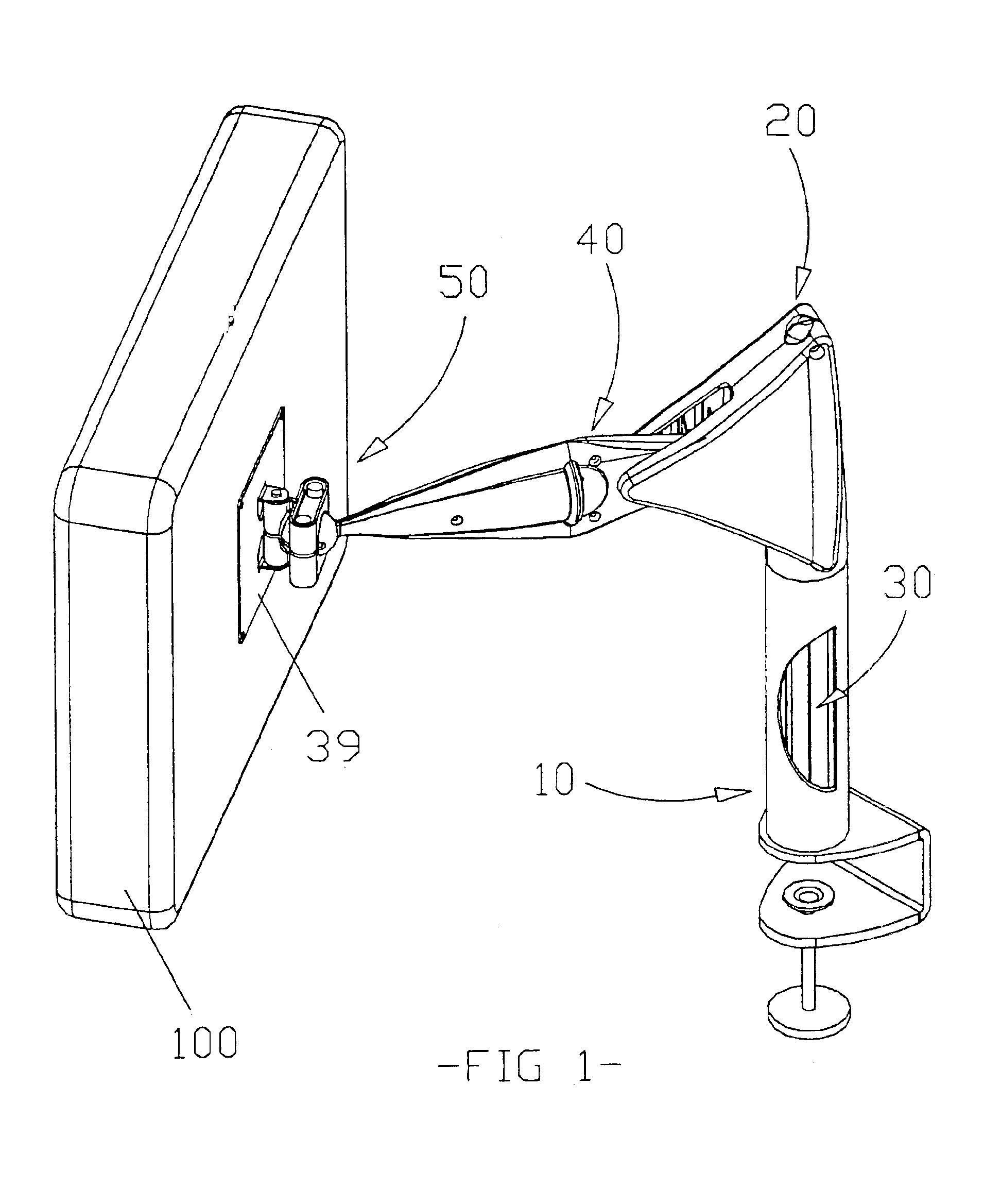
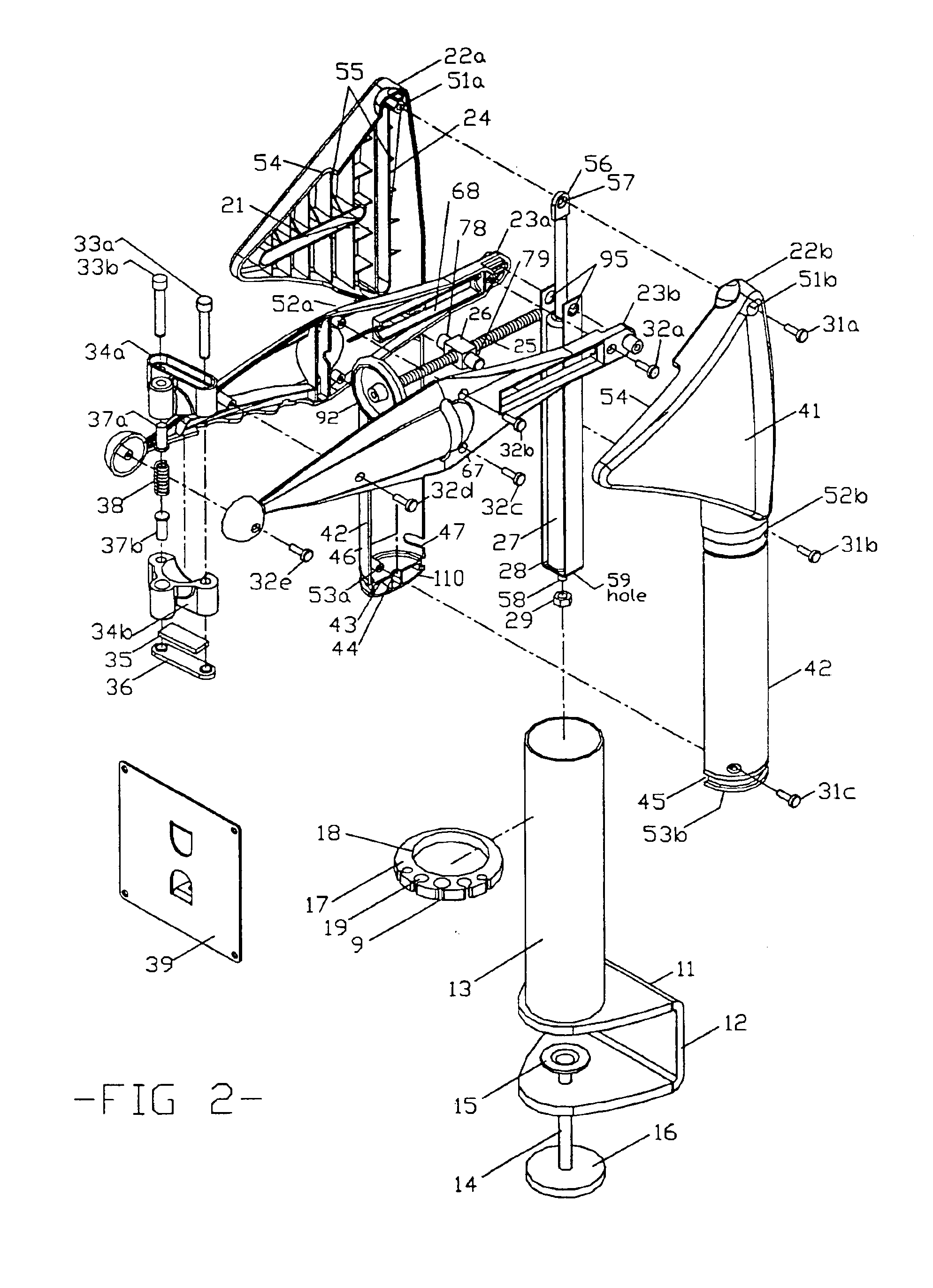
For purposes of description herein, the terms forward, rearward, upward, and downward relate to the load support mechanism as oriented in FIG. 2 where the viewer's left side is considered the forward direction. As shown in FIGS. 1 & 2 the adjustable position load support mechanism includes an anchoring arrangement 10, a load counterbalancing arrangement 30, a housing assembly 20, an arm assembly 40, and a ball and socket friction producing arrangement 50 that includes a mounting plate 39 for the attachment of a load 100, which is in this case a typical video display device.

The anchoring arrangement 10 is comprised of a channel shaped member 12. To one of the channel flange surfaces 1 is rigidly attached a hollow cylinder 13. On the same axis as the cylinder and extending through the opposite flange is a threadable member 14 and a disk shaped pad 15 which engages against the bottom surface of a desk overhang to enable a clamping operation to be effected when a clamping handle 16 is r...


PUM


Abstract

An improved mechanism for positioning loads of varying magnitudes, such as LCD displays, etc. The position of the load can be varied in height and angle according to the requirements of the user. The mechanism incorporates an adjustable sliding fulcrum, a support arm, a housing with four generally perpendicular channels, and a gas spring. The mechanism is initially manually adjusted for a particular load and then it automatically adjusts proportionally for the varying moments generated as the position of the load changes. The load is therefore evenly counterbalanced throughout its range of motion, and its position is maintained.

Description

BACKGROUND OF THE INVENTIONThis invention relates to video display support mechanisms, specifically an improved position adjustable support for flat panel Liquid Crystal Displays (LCD), A worker at a typical computer terminal may be required to spend long hours in a somewhat constrained physical posture. In order to maintain user comfort and create the proper ergonomic position of the video display it is often necessary for the user to be able to adjust the position of his video display. Various prior art mechanisms have created devices that give the user this adjustability, however, these previous designs have inherent mechanical and functional shortcomings.The typical prior art mounting systems contain various combinations of mounting brackets, support arms, friction locking knobs, ball gimbals, arcuate slots, mechanical springs, and gas springs. While the majority of these designs solve several of the typical usage problems, they are not very efficient support mechanism throughou...

Claims


Application Information

Patent Timeline
IPC IPC(8): F16M11/04F16M11/14
CPCF16M11/04F16M11/14F16M13/022F16M11/2021Y10S248/917F16M2200/068
Inventor CONNER, JOHN P.RUSSELL, ROBERT L.
Owner CONNER JOHN P
Why Eureka
Try Eureka