Connecting structure of grounded fitting for stitch jack board

A technology for socket boards and accessories, applied in the direction of connection, connection parts protective grounding/shielding device, electrical components, etc., can solve the problems of mold enlargement, ground terminal growth, deformation, etc., to achieve reliable electrical connection and ensure electrical connection. Effect

Inactive Publication Date: 2007-03-07
SMK CO LTD
View PDF12 Cites 0 Cited by
  • Summary
  • Abstract
  • Description
  • Claims
  • Application Information

AI Technical Summary

Problems solved by technology

[0005] However, once a plurality of conductive covers are connected in series to this grounding fitting, the strip-shaped or plate-shaped base will of course be lengthened, and there will be problems such as easy deformation during the electroplating operation.
And at the same time, there will be the problem of large mold
In particular, when forming a multi-connection, the gap between the connected conductive covers or the insulating cylinders with these conductive covers is offset, and the accumulation of the number will easily reduce the workability of the peripherals.
[0006] Therefore, although considering the combination of in-line configuration can ensure that multiple grounding fittings with the same number of conductive covers are used instead of one grounding fitting with the necessary number of conductive covers connected, at this time it is necessary to pull from the strip-shaped or plate-shaped base of each grounding fitting. Therefore, a relative number of connection holes for ground terminals must be formed on these printed substrates, resulting in restrictions on circuit encirclement.
In addition, especially at this time, the ground terminal extended from the strip-shaped or plate-shaped base of the upper ground fitting will increase, and problems such as deformation during plating operations will occur.

Method used


Image

  • Connecting structure of grounded fitting for stitch jack board
  • Connecting structure of grounded fitting for stitch jack board
  • Connecting structure of grounded fitting for stitch jack board

Examples


Embodiment Construction

[0043] According to an embodiment, referring to the accompanying drawings, the embodiment of the present invention is described in detail as follows.

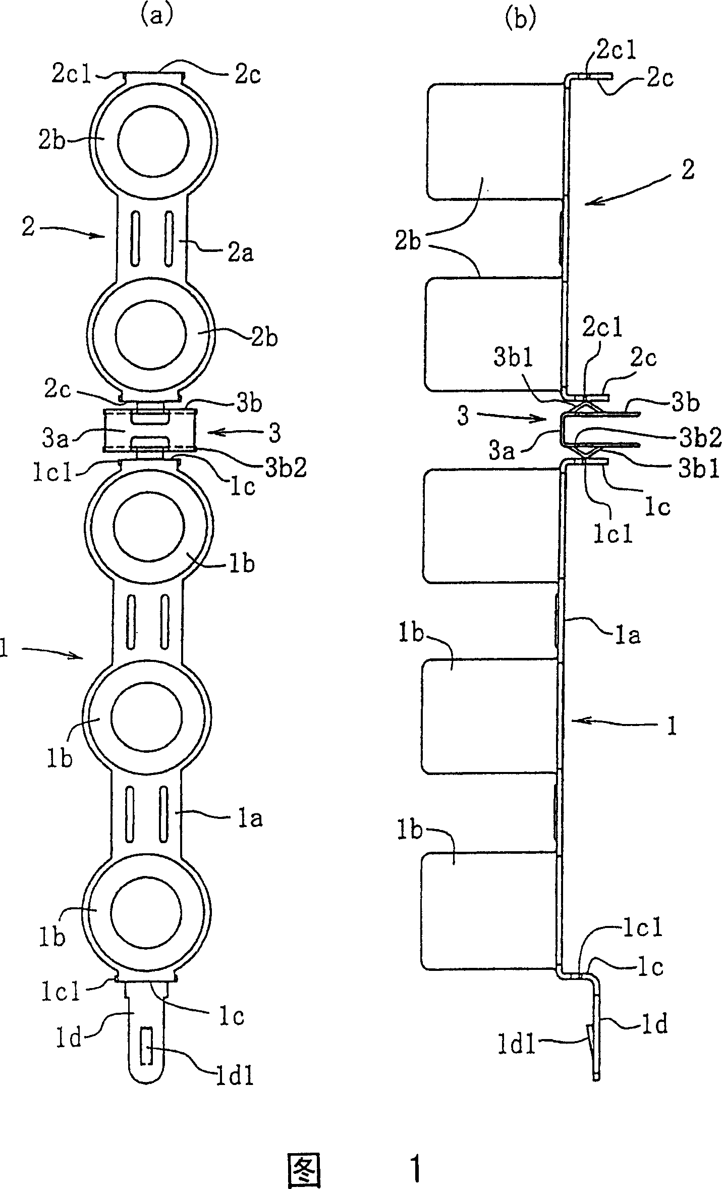
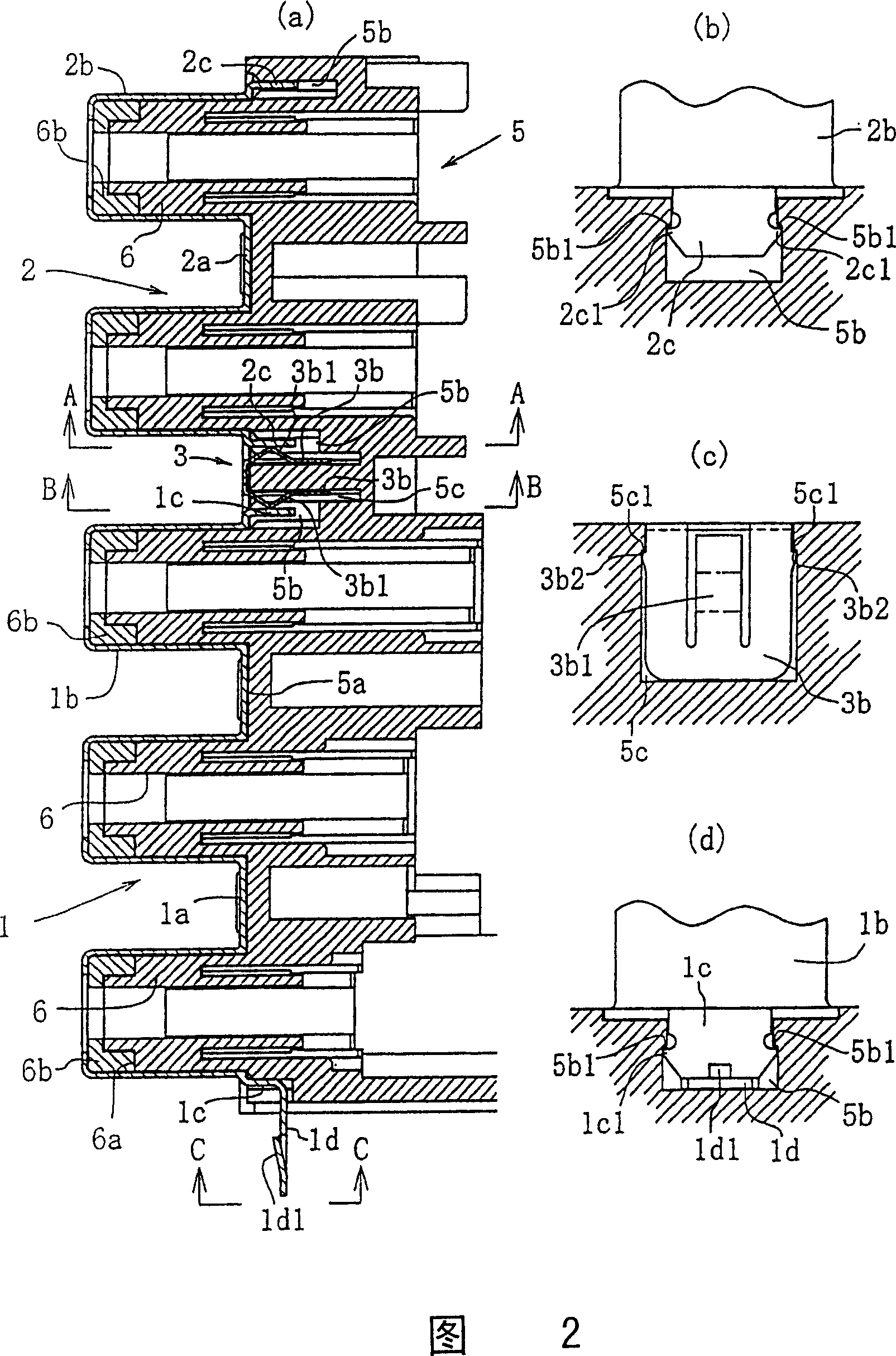
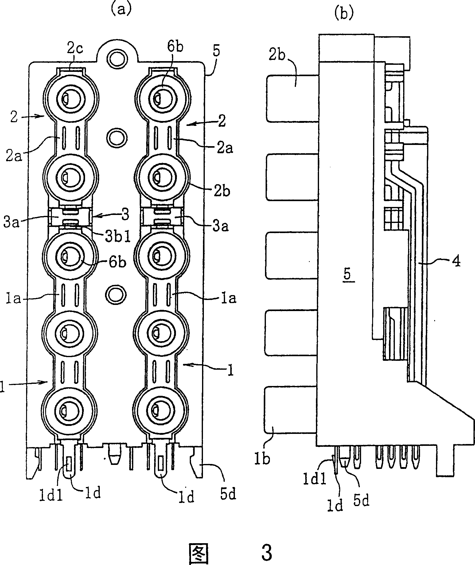
[0044] This embodiment is about the pin jacking board applicable to the connection structure of the ground fitting of the pin jacking board of the present invention, as shown in Figure 1 (a), (b), Figure 3 (a), (b) and Figure 7 (a) , as shown in (b), including: 3-connected grounding fittings 1; double-connected grounding fittings 2; terminal components 3 inserted therebetween; signal terminals 4, 4... integrally formed with unillustrated tabs; and setting these shells 5.

[0045] As shown in Figure 1 (a), (b) and Figure 5 (a), (b), the aforementioned 3-connected grounding fitting 1 includes: a strip-shaped base 1a; 3 conductive covers 1b, 1b erected in a row at regular intervals , 1b; engaging pieces 1c, 1c bent at right angles below both ends of the strip-shaped base 1a;

[0046] The strip-shaped base 1a is a strip-shaped co...


PUM


Abstract

PROBLEM TO BE SOLVED: To well respond to a request furnishing many pin jacks by electrically connecting and continuously installing a plurality of ground fittings having a small number of conductive caps. ŽSOLUTION: Conductive caps 1b, 1b are fit to five insulating cylinders 6 installed in the front of a housing 5, three string and two string ground fittings 1, 2 are arranged in series, and their belt-shaped base parts 1a, 2a are fit to a fitting recessed part 5a in the front of the housing 5. Connecting pieces 1c, 2c at both ends of the belt-shaped base parts 1a, 2a are inserted into and fixed to a locking groove 5b. A hanging piece 3b on both side of a terminal member 3 is inserted into and fit to a hanging piece locking groove 5c. An elastic contact piece 3b projecting from the hanging piece 3b comes in contact with the connecting pieces 1c, 2c of facing ground fittings 1, 2 and electrically connected, and a ground terminal 1d projecting from the lower end of the three string ground fittings 1 is connected to a printed circuit board. Ž

Description

technical field [0001] The present invention relates to a pin jack for electrically connecting a plurality of ground fittings to each pin jack row in a pin jack board having one or more pin jack rows arranged in series The connection configuration of the ground fitting in the board. Background technique [0002] The grounding fitting is formed by erecting a plurality of conductive covers in a row on a strip-shaped or plate-shaped base composed of conductive metal plates. Configure the tabs and install them on the shell to form pin jacks (Japanese Patent Registration Utility Model No. 2609978, page 2, right column, lines 2-8, Fig. 3; Registered Utility Model No. 2541017, Fig. 9, Fig. 10, Fig. 11), or a component that forms a pin insertion hole by being externally arranged on an insulating cylinder standing upright on the housing, and arranging tabs inside it. [0003] A grounding terminal protrudes from one end of the strip-shaped or plate-shaped base, and a reinforcing rib...

Claims


Application Information

Patent Timeline
Patent Type & Authority Patents(China)
IPC IPC(8): H01R13/652H01R33/76
Inventor 樱田英将
Owner SMK CO LTD
Why Eureka
Try Eureka