

Energy-saving oxygenation system in sewage treatment
A technology for sewage treatment and sewage pools, applied in the field of aeration systems, can solve problems such as low efficiency and high energy consumption of biochemical aeration systems, and achieve the effects of increasing solubility, reducing high energy consumption and high oxygenation efficiency.
- Summary
- Abstract
- Description
- Claims
- Application Information
AI Technical Summary
Problems solved by technology
Method used
Image


Examples
specific Embodiment approach 1
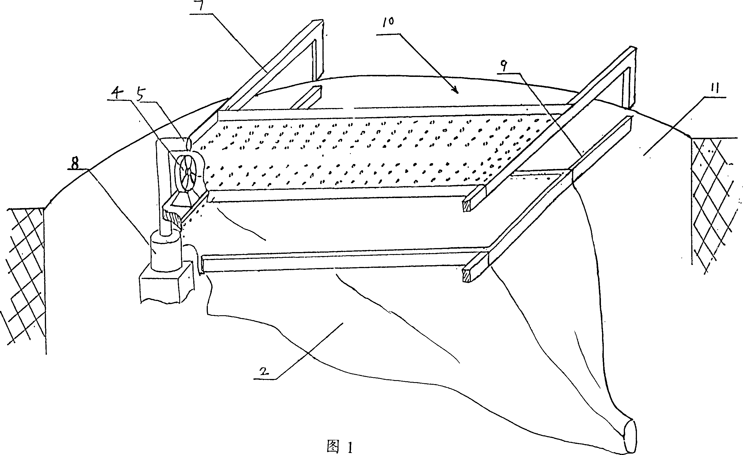
[0023] As shown in Figure 1, the energy-saving aeration system for sewage treatment, in the sewage pool 10, the shower pool 1 is fixed above the water surface by the support rod 7, and a funnel-shaped directional water tank 2 is set on the water surface below the shower pool, and the water tank 2 is directional. The water tank is fixed on the sewage tank wall 11 by the support rod 9, and the upper opening of the directional drain tank is higher than the water surface. A plurality of shower holes are arranged on the bottom surface of the shower pool 1, and the shower holes are arranged in a U shape on the bottom surface of the shower pool 1, and the outlet pipe 5 of the low-lift, high-flow submersible pump 8 arranged in the sewage is connected with the U-shaped array shower. The opening ends of the water holes are connected, and the fan 4 is arranged between the water shower pool 1 and the directional drain tank 2, and the fan 4 is corresponding to the opening ends of the water ...
specific Embodiment approach 2
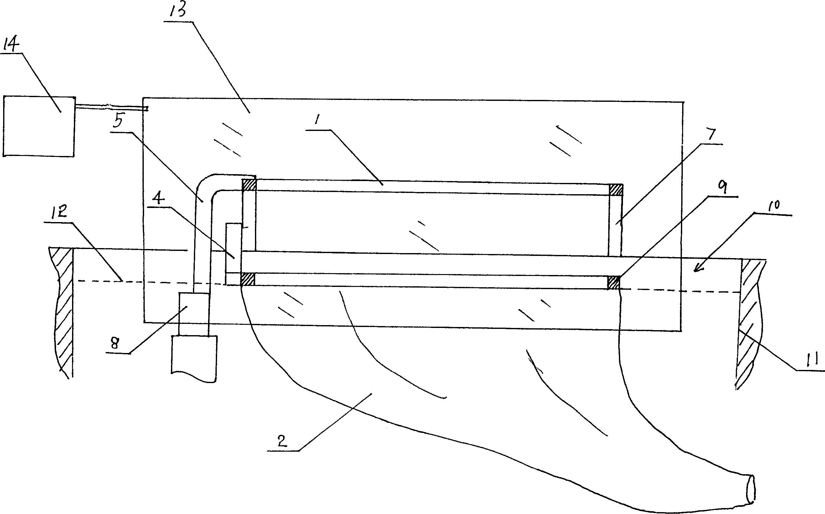
[0025] Such as figure 2 In the shown energy-saving aeration system for sewage treatment, in the sewage pool 10, the shower tank 1 is fixed above the water surface through the support rod 7, and the directional drain tank 2 is set on the water surface below the shower tank, and the directional drain tank passes through the support rod 9 Fixed on the sewage pool wall 11, the upper opening of the directional diarrhoea is higher than the water surface. A plurality of shower holes are arranged on the bottom surface of the shower pool 1, and the shower holes are arranged in a U shape on the bottom surface of the shower pool 1, and the outlet pipe 5 of the low-lift, high-flow submersible pump 8 arranged in the sewage is connected with the U-shaped array shower. The opening ends of the water holes are connected, and the fan 4 is arranged between the water shower tank 1 and the directional drain tank 6, and the fan 4 is corresponding to the opening ends of the water shower holes arrang...
specific Embodiment approach 3
[0027] Such as image 3 In the shown energy-saving aeration system for sewage treatment, the shower tank 1 is fixed above the water surface through the support rod 7 in the sewage tank 10, and a funnel-shaped directional water tank 2 is set on the water surface below the shower tank, and the directional water tank is supported by Rod 9 is fixed on the sewage pool wall 11, and the upper opening of the directional diarrhoea is higher than the water surface 12. A plurality of shower holes are arranged on the bottom surface of the shower pool 1, and the shower holes are arranged in a U shape on the bottom surface of the shower pool 1, and the outlet pipe 5 of the low-lift, high-flow submersible pump 8 arranged in the sewage is connected with the U-shaped array shower. The opening ends of the water holes are connected, and the fan 4 is arranged between the water shower pool 1 and the directional drain tank 2, and the fan 4 is corresponding to the opening ends of the water shower ho...
PUM
 Abstract
Description
Claims
Application Information