

Impedance-tuned connector
A technology of connectors and connector components, which is applied in the direction of connection, fixed connection, two-part connection device, etc., and can solve problems such as impedance changes
- Summary
- Abstract
- Description
- Claims
- Application Information
AI Technical Summary
Problems solved by technology
Method used
Image

Examples
Embodiment Construction
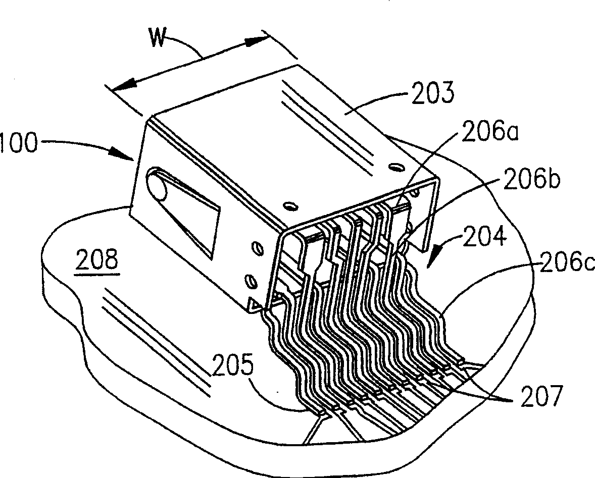
[0040] The present invention proposes improved connectors that are particularly useful in enhancing the performance of high-speed cables, particularly in input-output ("I / O") applications as well as other types of applications, and the present invention seeks to provide Measures of mechanical and electrical consistency are applied to facilitate improved performance of the connector alone and in combination with opposing connectors.
[0041] Many peripheral devices associated with electronic devices such as video cameras or camcorders transmit digital and other signals on different frequencies. Other devices related to the computer, such as the CPU part of the computer, operate at high speed for data transmission. High-speed cables are used to connect these devices to the CPU, and can also be used to connect two or more CPUs together in some applications. A particular cable can be adequately configured to carry these high speed signals, and will usually include differential si...
PUM
 Abstract
Description
Claims
Application Information