
Pulse valve performance detecting device and method
A detection device and pulse valve technology, which is applied in the direction of valve devices, measuring devices, diaphragm valves, etc., can solve the problems of different calibers, abnormal operation of equipment, and high energy consumption for cleaning dust, so as to achieve comprehensive detection content and avoid economic losses , the effect of accurate test results
- Summary
- Abstract
- Description
- Claims
- Application Information
AI Technical Summary
Problems solved by technology
Method used
Image

Examples
Embodiment Construction
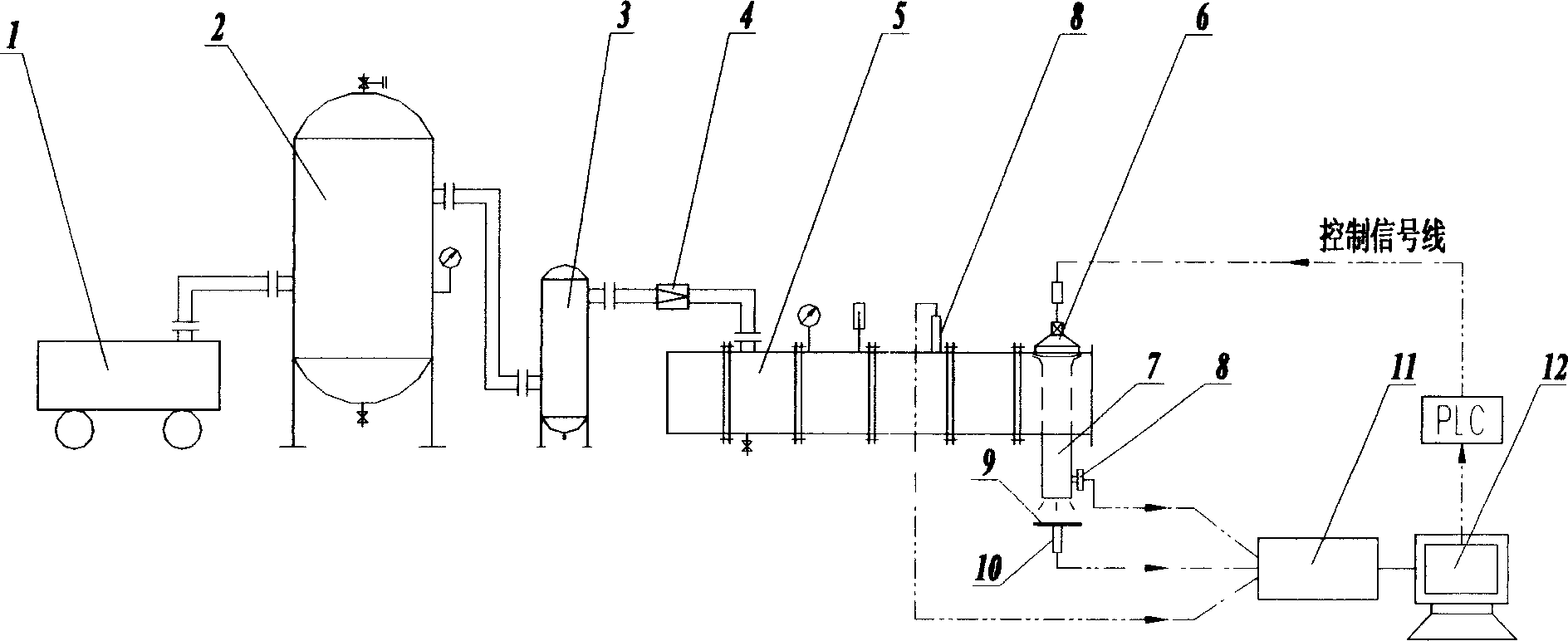
[0041] like figure 1 , the pulse valve performance testing device consists of air compressor 1, gas storage tank 2, oil-water separator 3, pressure reducing valve 4, pressure-stabilizing air bag 5, pulse valve 6 under inspection, blowing pipe 7, pressure sensor 8, and target 9 , an acceleration sensor 10, a data acquisition card 11, and a computer 12.
[0042] The air compressor 1, the gas storage tank 2, the oil-water separator 3 and the pressure-stabilizing air bag 5 are connected with a compressed air pipeline, and a pressure-reducing valve 4 is set on the pipeline between the oil-water separator 3 and the pressure-stabilizing air bag 5.
[0043] Set the blowing pipe 7 and the target 9 directly below the pulse valve 6 under inspection, the blowing pipe 7 is aligned with the target 9, and the wall of the blowing pipe 7 has a small hole;
[0044] Pressure sensor 8 is set respectively on the pressure-stabilizing air bag 5 and the opening of blowing pipe 7, and acceleration se...
PUM
 Abstract
Description
Claims
Application Information