Optical fiber projector

A technology of projectors and optical fibers, applied in the field of projectors, can solve problems such as complex structures, numerous mechanical parts, and difficult assembly of components, and achieve the effect of stable work and simple structure

Inactive Publication Date: 2006-02-01
HONG FU JIN PRECISION IND (SHENZHEN) CO LTD +1
View PDF1 Cites 6 Cited by
  • Summary
  • Abstract
  • Description
  • Claims
  • Application Information

AI Technical Summary

Problems solved by technology

[0004] In order to solve the problems in the prior art of the liquid crystal projectors that there are many optical components and mechanical components, the st

Method used


Image

  • Optical fiber projector
  • Optical fiber projector
  • Optical fiber projector

Examples


Embodiment Construction

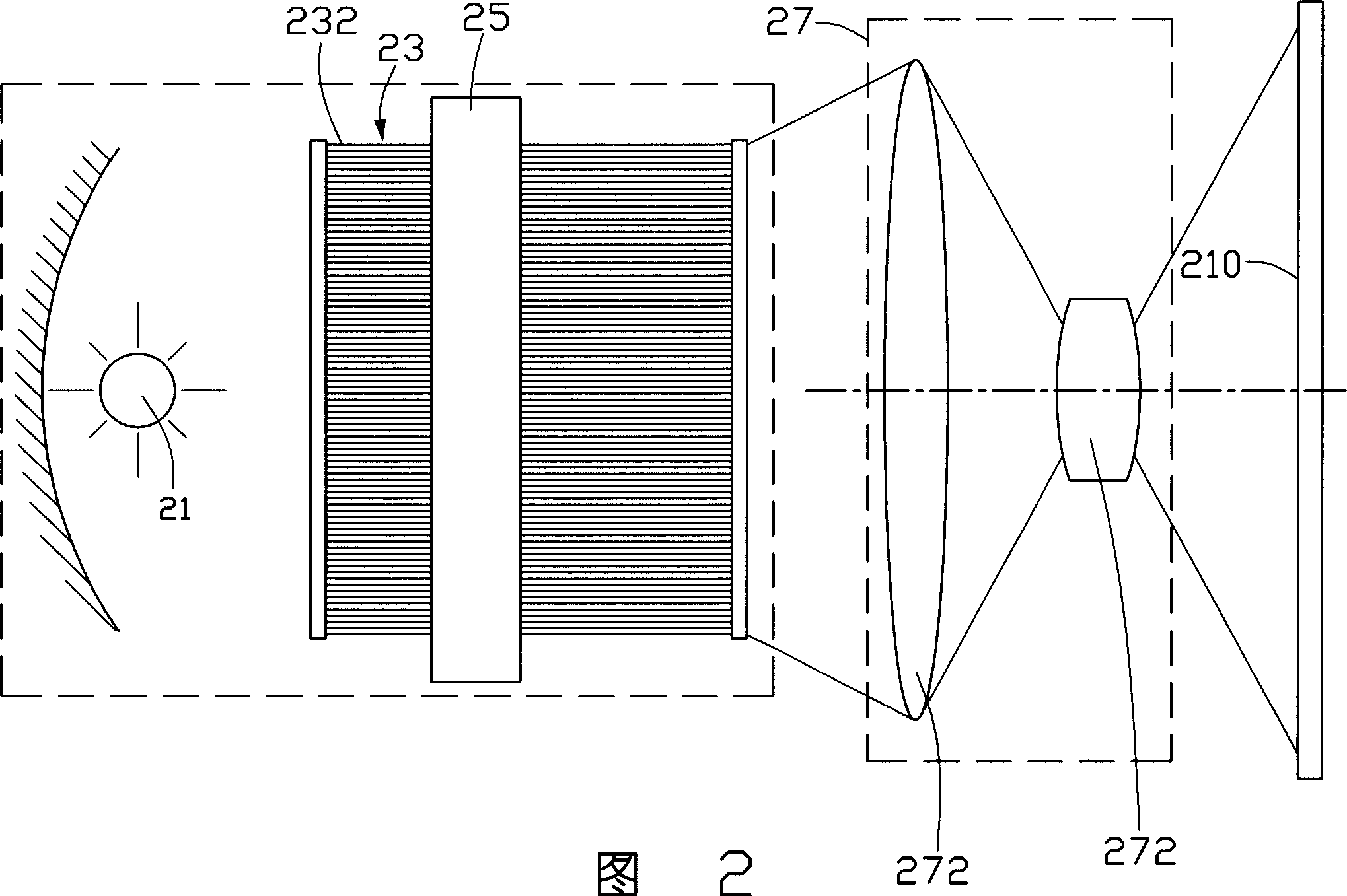
[0018] Please refer to FIG. 2 , which is a schematic structural diagram of the first embodiment of the fiber optic projector of the present invention. The fiber optic projector includes a light source 21, an optical fiber bundle 23, a brightness modulation system 25, and a projection lens group 27, wherein the optical fiber bundle 23 includes a plurality of optical fibers 232, and one end of the plurality of optical fibers 232 forms a light incident One end is used to receive the light emitted by the light source 21, and the other end constitutes an emitting end. The light brightness modulation system 25 is arranged between the light incident end and the light output end, and is used to control the bending degree of the optical fiber 232 in the optical fiber bundle 27, so as to realize brightness modulation. The projection lens group 27 includes at least one projection lens 272 capable of projecting the light signal modulated by the brightness modulation system 25 onto the scr...


PUM


Abstract

An optical fibre projector consists of light source, optical fibre bundle, brightness adjusting device, projection lens set, colour filter, light coupling component, visual light bandpass filter and diffusion sheet. It is featured as forming optical fibre bundle by a numbers of optical fibres with light incoming end and light outgoing end , setting brightness adjusting device between said two ends for changing the bending level of each optical fibre to adjust outgoing light intensity at each light outgoing end and projecting out outgoing light by projection lens set.

Description

【Technical field】 [0001] The invention relates to a projector, in particular to a fiber optic projector. 【Background technique】 [0002] With the continuous development of science and technology in recent decades, various new display technologies have emerged as the times require. The display technologies currently used in projectors mainly include cathode ray tube (Cathode RayTube), liquid crystal display (Liquid Crystal Display), digital light processing (DigitalLight Processing) and other technologies. [0003] A kind of prior art liquid crystal projector can refer to the Chinese patent application No. 99109766 disclosed on January 17, 2001, as figure 1 As shown, the liquid crystal projector at least includes a parallel light source device 100 , a negative lens group 108 and a liquid crystal module 115 . The parallel light source device 100 includes a light source 101, a reflector 102, a condenser lens 104, and a positive lens 106, wherein the light emitted by the light...

Claims


Application Information

Patent Timeline
IPC IPC(8): G02B27/18G02B6/32
Inventor 李俊佑
Owner HONG FU JIN PRECISION IND (SHENZHEN) CO LTD
Why Eureka
Try Eureka