Front self locking fixing pin plate for lumbar vertebra

A fixation plate and fixation nail technology, applied in the direction of fixator, internal fixator, internal bone synthesis, etc., can solve the problems of aggravated neurological dysfunction, large trauma, long time, etc., and achieves fast recovery, less trauma, and simple structure for patients. Effect

A fixation plate and fixation nail technology, applied in the direction of fixator, internal fixator, internal bone synthesis, etc., can solve the problems of aggravated neurological dysfunction, large trauma, long time, etc., and achieves fast recovery, less trauma, and simple structure for patients. Effect

CN1748655AActive Publication Date: 2006-03-22CHONGQING FWS MEDICAL INSTR CO LTD

Image

  • Front self locking fixing pin plate for lumbar vertebra
  • Front self locking fixing pin plate for lumbar vertebra
  • Front self locking fixing pin plate for lumbar vertebra

Examples


Embodiment Construction

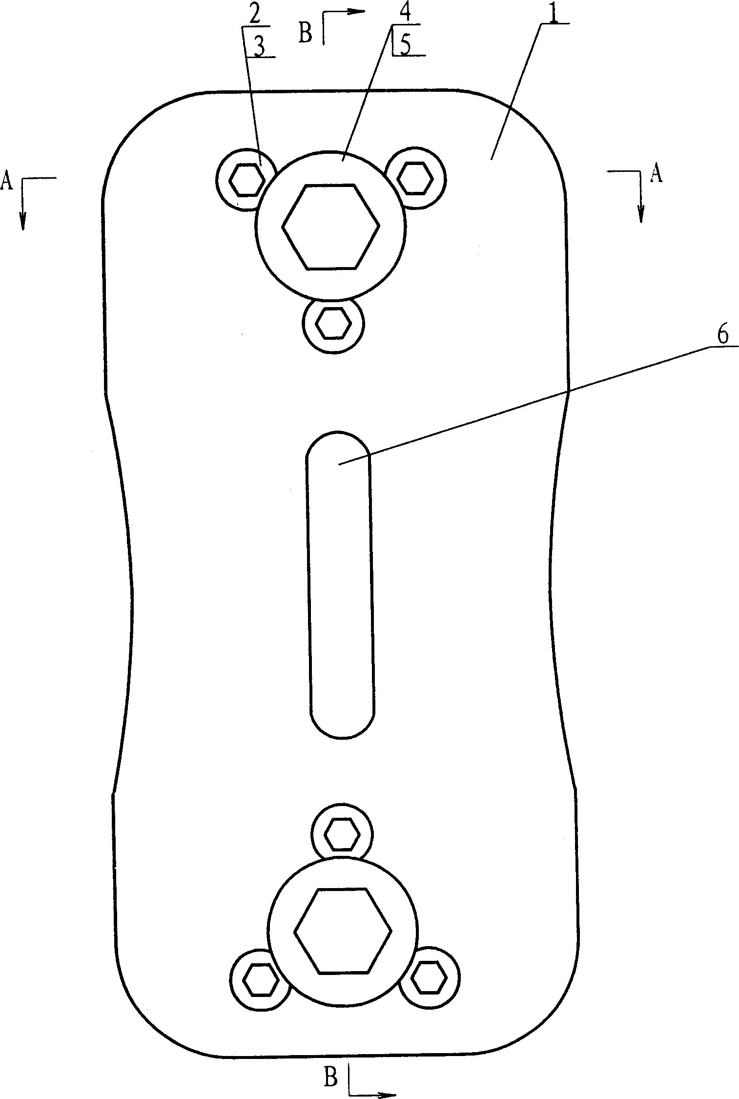
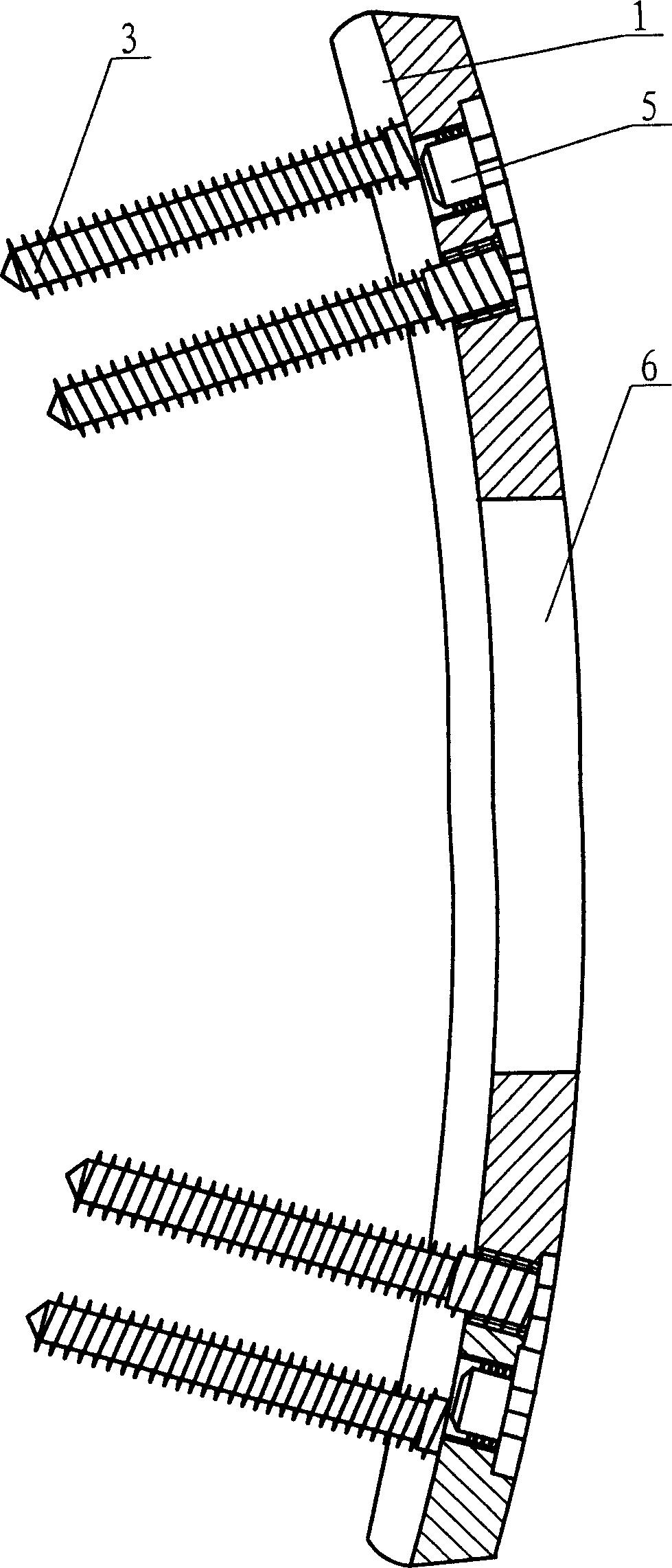
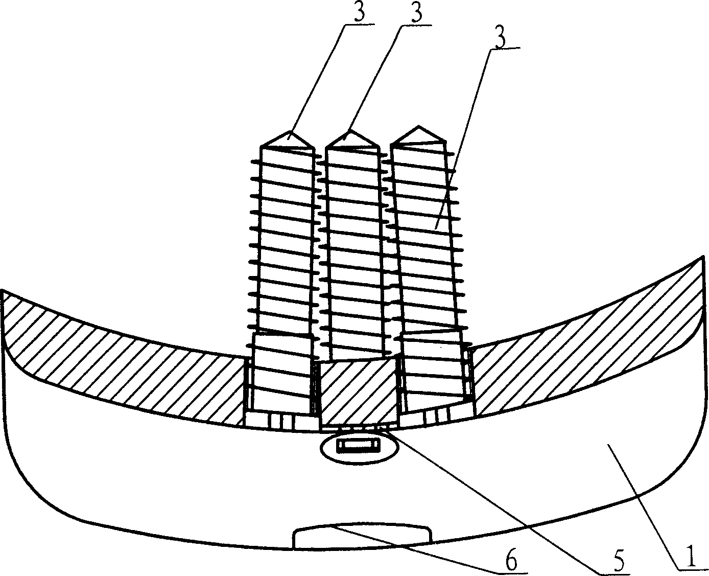
[0015] Embodiments of the present invention are described below with reference to the accompanying drawings. Such as figure 1 , figure 2 , image 3 , Figure 4 , Figure 5 As shown, a self-locking nail plate in front of the lumbar vertebral body includes a fixed plate 1 and a fixed screw 3. The fixed plate 1 is in the shape of a circular arc consistent with the lumbar lordosis along the axial direction, and the fixed plate is aligned with the lumbar vertebral body in the transverse direction. The front arc surface is in the same arc shape, and the axial ends of the fixed plate 1 are respectively provided with three threaded holes 2 with countersunk heads distributed in an equilateral triangle, wherein two threaded holes are parallel to the lateral sides, each Fixing screw 3 is set in the threaded hole, an arc-shaped otch is provided on the outer circumference of the nail head top of the fixing screw, and the center between the three threaded holes is also provided with a ...


PUM


Abstract

The present invention relates to internal lumber vertebra fixture and is especially one front locking fixture plate with screws for lumber vertebra. The front locking fixture plate includes fixing plate and fixing screw, and features the fixing plate in the kurtorachic shape and with 2x3 screw holes with fixing screws, and the screws with arc cut in the head and locked with two other screws separately. The present invention has simple structure, high fixing strength, high safety and small operation wound.

Description

1. Technical field [0001] The invention belongs to a medical internal plant device, and relates to an internal fixation device of a lumbar vertebral body, in particular to a self-locking fixation nail plate in front of a lumbar vertebral body. 2. Background technology [0002] Spinal internal fixation is a basic and important technique for treating spinal injuries, especially in the treatment of lumbar injuries. Among the internal fixation devices currently used for the lumbar spine, there are mainly posterior (or rear) fixation devices for the lumbar spine, lateral fixation devices for the lumbar vertebral body, and frontal fixation devices for the lumbar vertebral body. [0003] Various vertebral screw solid devices are commonly used in the lumbar posterior (or rear) fixation device at present, and the lumbar vertebral body is fixed through the connection between the screw and the rod. This type of fixation device has the following defects: (1) the installation of the fix...

Claims


Application Information

Patent Timeline
22 Mar 2006
Publication
CN1748655A
IPC
A61B17/70
Inventors
周强; 许建中