Magnetic driven rotation gas distribution device in gas-fluid etc. heterogeneous system

A technology of gas distribution device and multi-phase system, which is applied in the direction of chemical method, dissolution, chemical/physical/physicochemical fixed reactor for reacting liquid and gas medium, and can solve the problem of fluid mechanical characteristics, gas distribution device, etc. Single, complex equipment and other problems, to achieve the effect of wide distribution, simplified equipment, easy processing, manufacturing and maintenance

Inactive Publication Date: 2006-07-05
INST OF PROCESS ENG CHINESE ACAD OF SCI
View PDF0 Cites 8 Cited by
  • Summary
  • Abstract
  • Description
  • Claims
  • Application Information

AI Technical Summary

Problems solved by technology

[0009] 1) The microbubbles generated by nozzles or porous materials are generally larger than 50 microns, limited by the equipment, the air distribution device is relatively simple, and it is difficult to improve the fluid mechanical properties in the equipment
[0010] 2) The microbubbles generated by the stirring device are generally larger than 50 microns, which consumes a lot of energy and has a narrow application range, so it is rarely used in the field of chemical separation
[0011] 3) The microbubbles produced by the dissolved gas-precipitation and electrolysis devices are all smaller than 50 microns, but the equipment is complicated, the investment is large, and the energy consumption is also large

Method used


Image

  • Magnetic driven rotation gas distribution device in gas-fluid etc. heterogeneous system
  • Magnetic driven rotation gas distribution device in gas-fluid etc. heterogeneous system

Examples


Embodiment 1

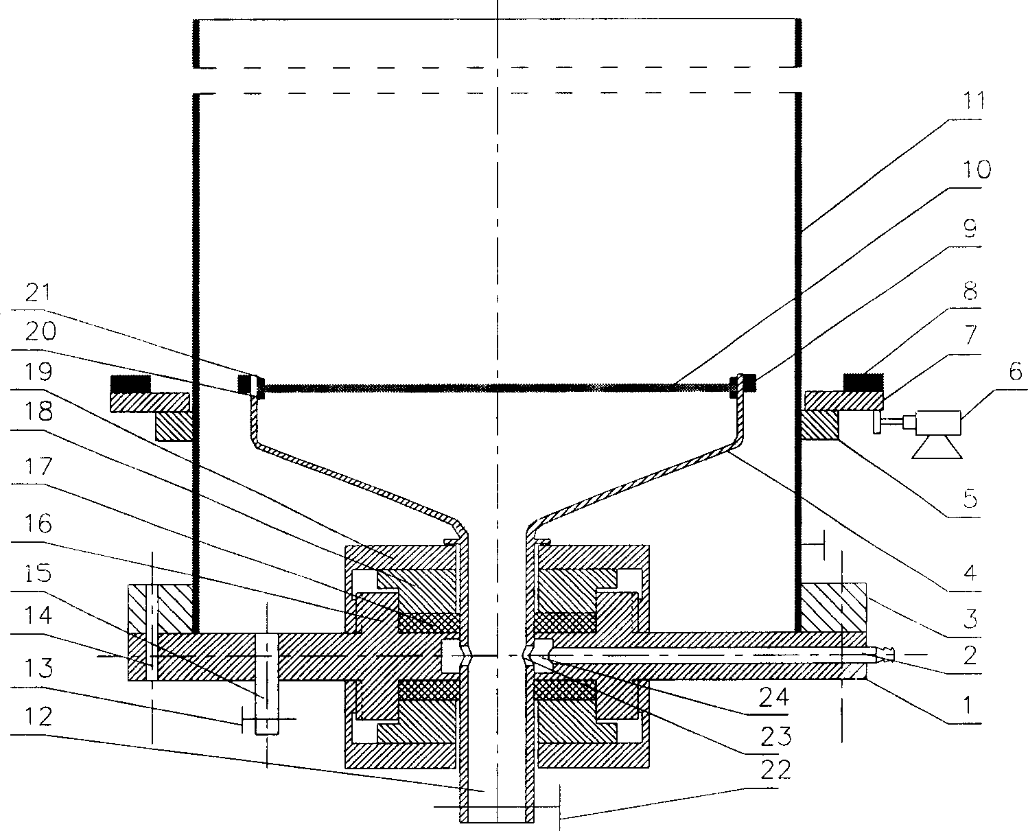
[0043] Attached figure 1, make the distribution plate support 4 and the rotating hollow shaft 12 with stainless steel, and weld the distribution plate support frame 20 on the distribution plate support 4, and seal and fix an average aperture on the support frame 20 by the pressure plate 21 on the distribution plate. The 80mm porous sintered titanium plate 10 is used as the gas distribution plate, and two permanent magnets 9 are symmetrically installed on the side wall of the distribution plate support 4, and two gas introduction holes 23 are opened on the rotating hollow shaft 12 to make the distributor support plate 1 On the support plate 1, the gas inlet pipe hole 2, the sealing support ring 16 with outer thread and the sewage pipe hole are opened. The pressure ring 19 is sealed and connected with the distributor tray 1, and the tower 11 with an inner diameter of 10 cm and a height of 1 m is used as the main body of the tower, and the main body of the tower is sealed and con...

Embodiment 2

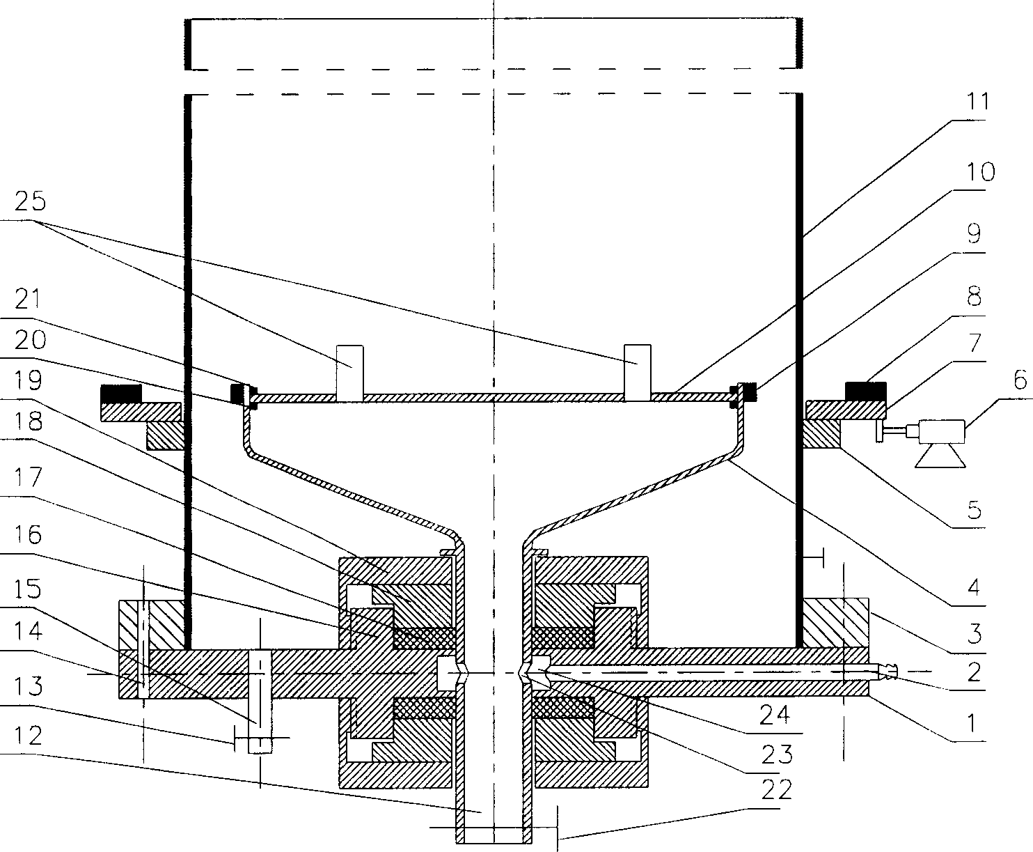
[0045] Attached figure 2 , make the distribution plate support 4 and the rotating hollow shaft 12 with stainless steel, and weld the distribution plate support frame 20 on the distribution plate support 4, and seal and fix a support plate 10 supporting the porous cylinder on the support frame 20 by the distribution plate pressing plate 21 Four porous cylinders 25 with an average aperture of about 20 microns and a height of 40 mm are symmetrically installed on the support plate 10 as gas distribution heads, and two permanent magnets 9 are symmetrically installed on the side wall of the distribution plate support 4. Two gas inlet holes 23 are opened on the hollow shaft 12 to make the distributor support plate 1, and the gas introduction pipe hole 2, the sealing support ring 16 with outer screw thread and the sewage pipe hole are opened on the support plate 1, and the distribution plate support 4 and The rotating shaft 12 is sealed and connected with the distributor tray 1 throu...

Embodiment 3

[0047] Example 3. Traditional stationary perforated plate gas distribution method for gas-liquid two-phase flow in quiet bubbling zone

[0048] With the magnetic transmission rotary gas distribution device of the multiphase system such as gas-liquid that is made in embodiment 1, add tap water in tower device (11), height is 950mm, and the nitrogen in the compressed steel cylinder passes air inlet pipe (2), The gas distribution chamber (24) and the gas introduction hole (23) on the hollow shaft pass through the gas distribution plate (10) and enter the tower, the gas volume flow rate is 220ml / min, the water phase and the gas phase are operated in countercurrent, the volume flow rate is 570ml / min min, do not start the motor (6) to ensure that the gas distribution plate (10) is still, and when the two-phase flow reaches a steady state, use saturated potassium nitrate solution as a tracer, and use the online automatic conductivity method liquid phase back-mixing measurement equipme...


PUM


Abstract

The invention relates to a magnetic driving rotary gas distributor equipment of gas-liquid multi-phase system. It includes a tower device with magnetic driving device, the rotary-type gas distributor can be directly rotated in the tower bottom to make gas distribution. The gas distributor is driven by rotary permanent magnetic field produced by magnetic driving device and rotated so as to implement goal of rotary gas distribution. In the supporting disk of the gas distributor a gas ingress pipe hole is set, and the ring-shaped gas distribution cavity chamber in the supporting disk and the gas-feeding circular hole on the rotary hollow shaft can be used for making gas distribution, in the bottom end of the rotary hollow shaft a cleaning pollution-discharging valve is mounted.

Description

technical field [0001] The invention relates to a magnetically driven rotating gas distribution device for multiphase systems such as gas-liquid, in particular to a magnetically driven rotating gas used in gas-liquid two-phase flow or gas-liquid-solid three-phase flow distribution device. Background technique [0002] Gas-liquid two-phase flow or gas-liquid-solid three-phase flow is widely used in the chemical industry, and plays a very important role in various chemical unit operations, such as in the design and operation of gas-liquid and gas-liquid-solid reactors. In operation, the effect of the gas distribution device directly affects the hydrodynamic characteristics of the reactor, such as the size of the bubbles, the amount and distribution of the gas holdup, and the mixing degree of the liquid and gas phases, etc., which in turn affects the reaction yield and selectivity. In the field of biochemical industry, especially food and bio-fermentation industries, gas-liqui...

Claims


Application Information

Patent Timeline
Patent Type & Authority Applications(China)
IPC IPC(8): B01F3/04B01J10/00B01J19/18
Inventor 孙兴华常志东安振涛申淑锋胡欣刘吉刘会洲
Owner INST OF PROCESS ENG CHINESE ACAD OF SCI
Why Eureka
Try Eureka