Short-circuit fault current limiter

A fault current limiter, short-circuit fault technology, applied in circuit devices, emergency protection circuit devices, protection against overcurrent, etc. Circuit structure, the effect of improving the current limiting capability

Inactive Publication Date: 2006-10-11
INST OF ELECTRICAL ENG CHINESE ACAD OF SCI
View PDF2 Cites 5 Cited by
  • Summary
  • Abstract
  • Description
  • Claims
  • Application Information

AI Technical Summary

Problems solved by technology

At the same time, the current flowing through the bias power supply is often 2 to 3 times the grid current, and must meet the requirements of the current change in the non-fault state and the fault state. Therefore, the realization of the bias power supply has certain technical difficulties and high requirements. cost

Method used


Image

  • Short-circuit fault current limiter
  • Short-circuit fault current limiter
  • Short-circuit fault current limiter

Examples


Embodiment Construction

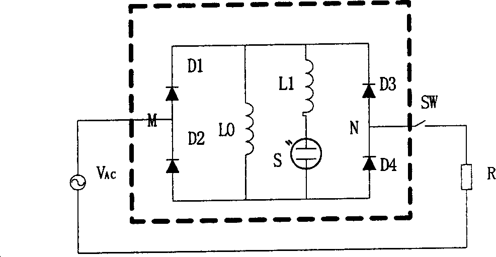
[0022] The present invention will be further described below in conjunction with accompanying drawing and specific embodiment:

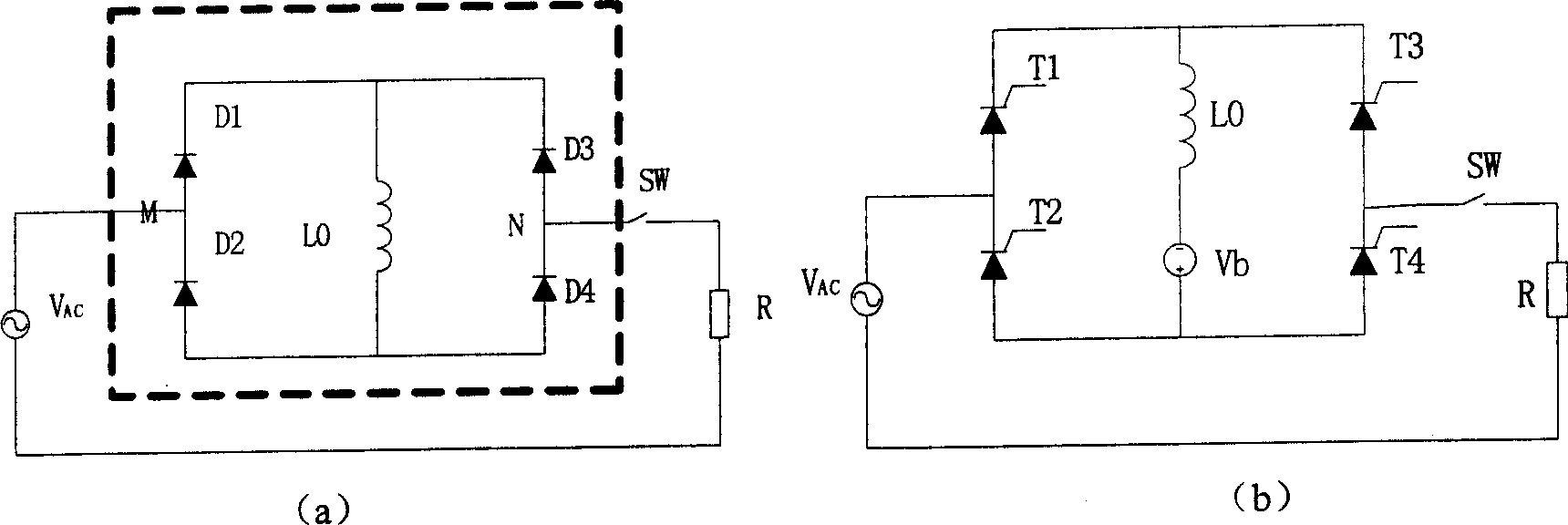
[0023] Such as figure 2 As shown, Embodiment 1 of the present invention is a single-phase short-circuit fault current limiter. The existing single-phase short-circuit fault current limiter is composed of a single-phase rectifier bridge composed of four diodes D1, D2, D3, D4 and a current-limiting inductance L0. On this basis, a series loop of an auxiliary inductance L1 and a discharge tube S is connected in parallel to the current-limiting inductance L0 in the existing short-circuit fault current limiter, and the bias power supply is canceled at the same time to form a single-phase short-circuit fault current limiter. SW is the circuit breaker, Vac is the line AC power supply, and R is the load equivalent resistance.

[0024] There is no fault in the line, that is, in the steady state, the diodes D1, D2, D3, and D4 of the single-phase rectifier br...


PUM


Abstract

The related discharge-form current limiter for short fault is formed by paralleling an auxiliary inductance and a discharge tube on current device. The production can not only automatic limit fault current peak, but also limits the rise rate and stable value at any time without any control circuit. This invention reduces cost and improves power network reliability and security.

Description

technical field [0001] The invention relates to a short-circuit fault current limiter, in particular to a fault current limiter for transmission and distribution networks. Background technique [0002] With the rapid development of the national economy, the society's demand for electricity continues to increase, which drives the continuous development of the power system. The capacity of single machines and power plants, the capacity of substations, and the load of cities and industrial centers continue to increase, which makes the interconnection of power systems , the level of short-circuit current in the power grid at all levels is increasing continuously, and the destructiveness of short-circuit faults to the power system and its connected electrical equipment is also increasing. Moreover, while the demand for electric energy is increasing day by day, people also put forward higher requirements for power quality, power supply reliability and security. However, the trans...

Claims


Application Information

Patent Timeline
Patent Type & Authority Applications(China)
IPC IPC(8): H02H9/02H02H3/08
Inventor 张志丰肖立业
Owner INST OF ELECTRICAL ENG CHINESE ACAD OF SCI
Why Eureka
Try Eureka