Supercharge Your Innovation With Domain-Expert AI Agents!

Connector

A connector and receiving cavity technology, applied in the direction of connection, two-part connection device, parts of the connection device, etc., can solve the problems of increasing cost and increasing the number of components

Inactive Publication Date: 2007-07-04
YAZAKI CORP
View PDF1 Cites 8 Cited by
  • Summary
  • Abstract
  • Description
  • Claims
  • Application Information

AI Technical Summary

Problems solved by technology

However, since the connector requires the front end locator 400 separate from the connector housing 200, it results in an increase in the number of components and thus increases the cost.

Method used


Image

  • Connector
  • Connector
  • Connector

Examples


Embodiment Construction

[0099] first preferred embodiment

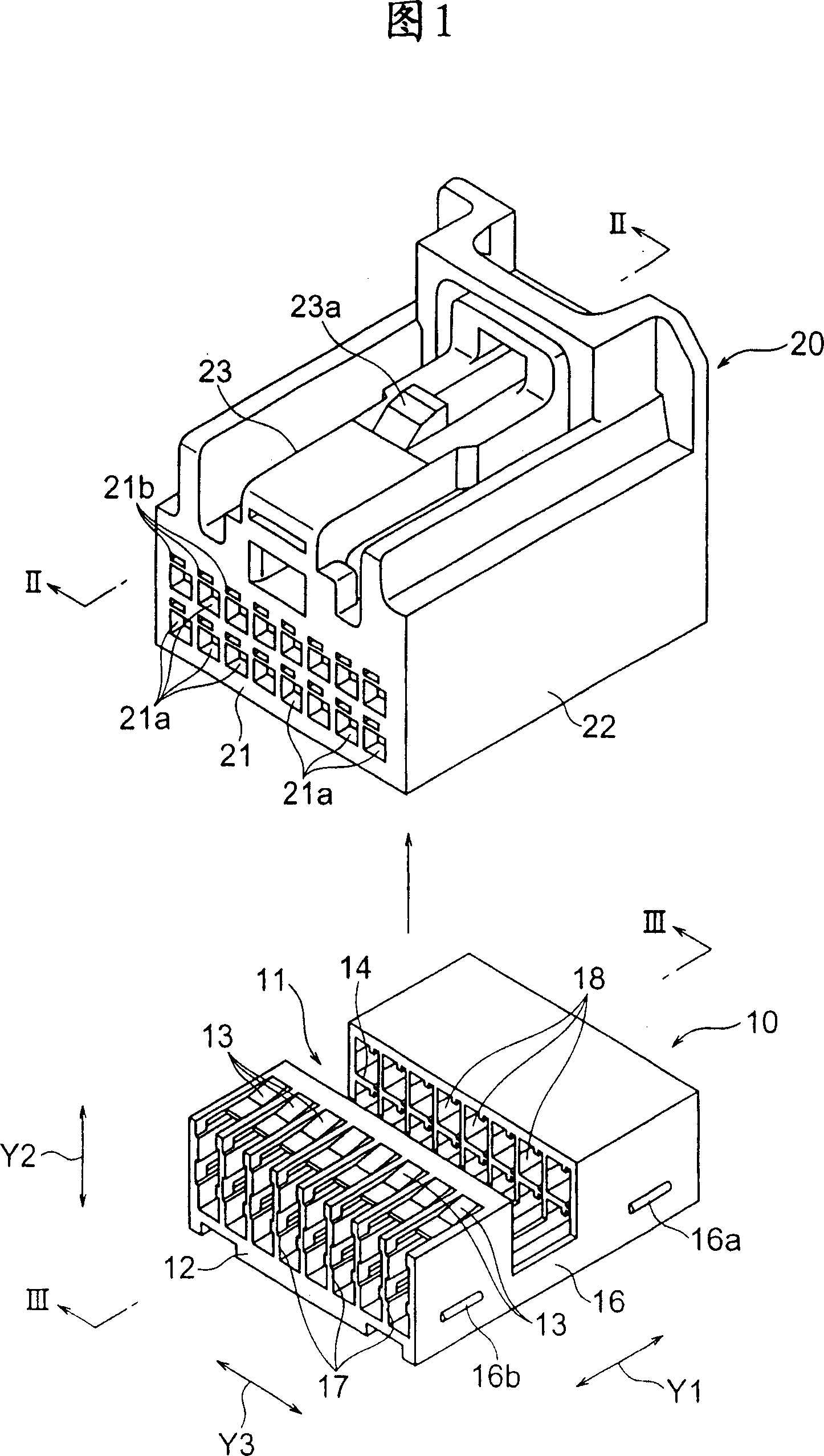
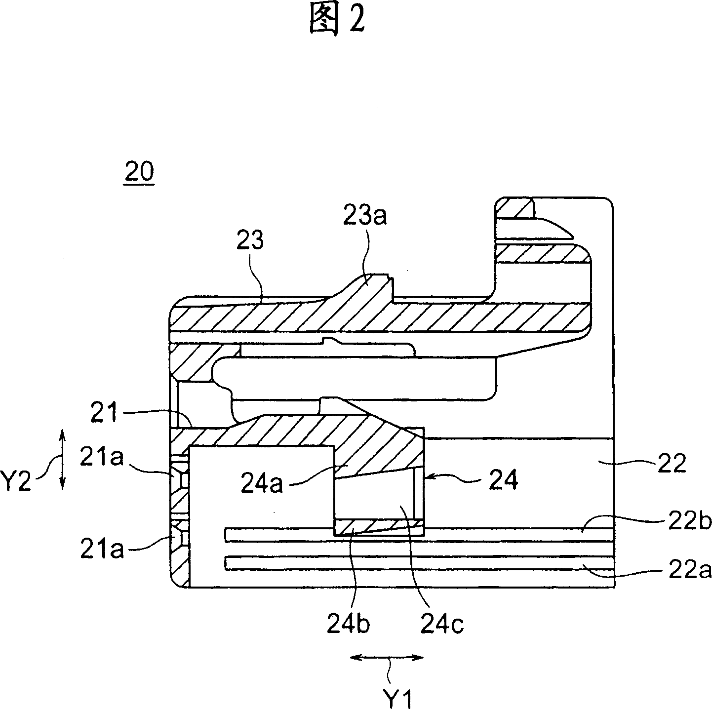
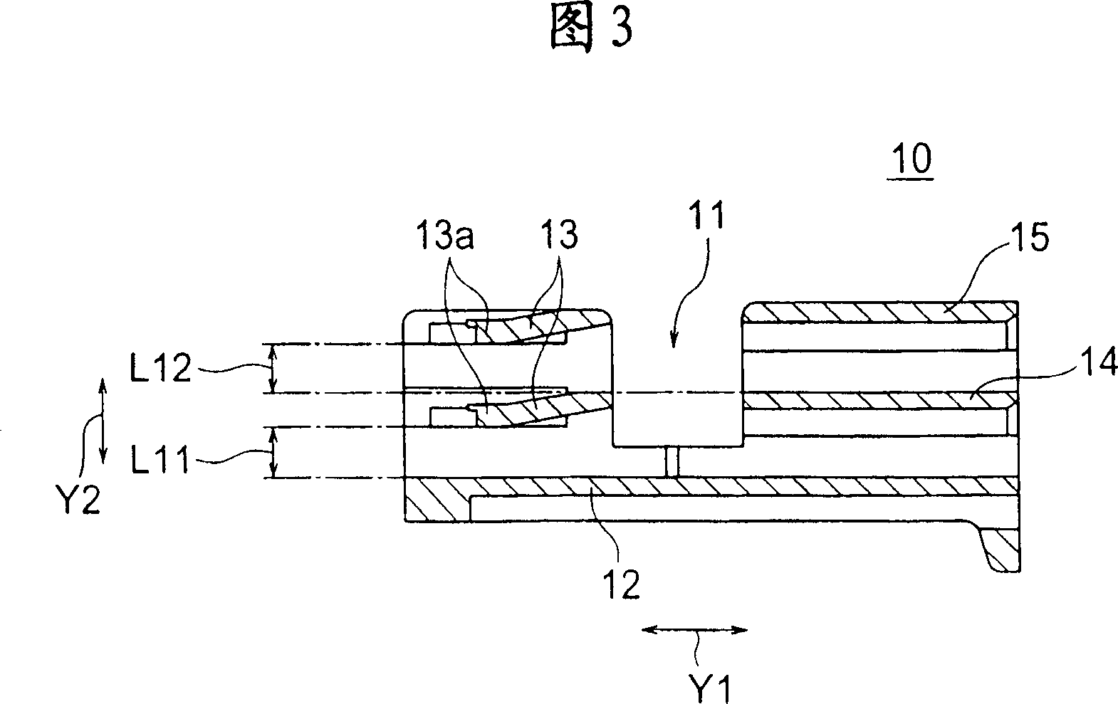
[0100] Next, a first preferred embodiment of the present invention will be described with reference to the drawings. FIG. 1 is an exploded perspective view of a first preferred embodiment of a connector according to the present invention, showing a cover (ie, exterior) 20 and housing 10 . FIG. 2 is a cross-sectional view of the outer cover 20 taken along line II-II of FIG. 1 . FIG. 3 is a cross-sectional view of the casing 10 taken along line III-III of FIG. 1 . Fig. 4 is a cross-sectional view of the connector in a temporary locking position. Figure 5 is a cross-sectional view of the connector in a fully locked position. Fig. 6 is a partially enlarged cross-sectional view of the connector at a temporary locking position. Fig. 7 is a partially enlarged cross-sectional view of the connector in a fully locked position. FIG. 8 is a perspective view of an outer cover 20 according to another preferred embodiment. FIG. 9 is a front view of t...


PUM


Abstract

The connector includes: a housing including a terminal receiving cavity and a terminal locking gun for locking a terminal received in the terminal receiving cavity; and an exterior including a front portion and a partition portion, wherein the front portion covers the terminal in the longitudinal direction The end side of the housing has a mating terminal insertion hole penetrating the terminal receiving cavity, and the partition plate portion is installed into the housing from an installation direction at right angles to the longitudinal direction of the terminal and is locked to the housing in a temporary locking position and a full locking position. In the body, the temporary locking position allows the terminal to be inserted into the terminal receiving cavity, and the full locking position is used to lock the terminal and prevent the terminal from protruding from the terminal receiving cavity, wherein the front part and the partition part form an integral body.

Description

technical field [0001] The present invention relates to a connector, in particular to such a connector comprising: a connector housing having a terminal locking lance (terminal locking lance) that locks the terminals first; and a partition that locks the terminals again, wherein the partition is removed from Fit into the connector housing at right angles to the longitudinal intersection of the terminals. Background technique [0002] Hitherto, as the above-mentioned connector, for example, a connector shown in FIG. 32 is known (Japanese Patent Application Laid-Open No. H7-296895). This conventional connector includes: a connector housing 200 having a terminal locking gun 201 that first locks a terminal 100 accommodated in a terminal receiving cavity; The 300 is inserted into the connector housing 200 from a direction Y2 intersecting the longitudinal direction Y1 of the terminal 100 at right angles. [0003] As shown in FIG. 32 , the front portion of the connector housing 2...

Claims


Application Information

Patent Timeline
Patent Type & Authority Applications(China)
IPC IPC(8): H01R13/42H01R13/436H01R24/00
CPCH01R13/506H01R13/4362H01R13/6272
Inventor 渡边哲也儿玉晋司铃木谦志泽入薰
Owner YAZAKI CORP
Features
  • R&D
  • Intellectual Property
  • Life Sciences
  • Materials
  • Tech Scout
  • Unparalleled Data Quality
  • Higher Quality Content
  • 60% Fewer Hallucinations
Learn More