Apparatus for driving optical-reflector

an optical reflector and accessory technology, applied in the direction of optical elements, electronic commutation motor control, instruments, etc., can solve the problems of reducing affecting the service life of the device, and the intrinsic features of the zoom lens may be deteriorated, so as to reduce the size of the driving apparatus, the effect of enhancing the utilization of space and simple structur

Active Publication Date: 2019-04-16
JAHWA ELECTRONICS
View PDF7 Cites 7 Cited by
  • Summary
  • Abstract
  • Description
  • Claims
  • Application Information

AI Technical Summary

Benefits of technology

[0013]The present disclosure is designed to solve the problems of the related art, and therefore the present disclosure is directed to providing an apparatus for driving an optical-reflector for OIS, which may enhance precision in driving by applying a guide structure with a rounded shape where rotation of an optical-reflector for changing a path of light is physically supported and guided, and also minimize a driving force required for rotating the optical-reflector.
[0021]According to an embodiment of the present disclosure, since optical image stabilization in one axial direction may be performed by an optical-reflector which changes a path of light and optical image stabilization in another axial direction may be performed by a lens, the driving apparatus may be implemented with a simple structure in comparison to an existing technique where optical image stabilization in all axial directions are performed by a lens, and also space utilization of the driving apparatus may be further enhanced, which may minimize the size of the driving apparatus.
[0022]According to an embodiment of the present disclosure, since the rotation of the optical-reflector for changing a path of light is physically supported and guided by the guiding structure with a curvature and the point-contact of the balls, which may improve the precision of optical image stabilization and also minimize a power required for the optical image stabilization.
[0023]In addition, since a coupling structure of components or elements may be simplified in the present disclosure, the assembling process may be performed more rapidly and accurately, thereby lowering a defective fraction and further enhancing the production efficiency.

Problems solved by technology

Therefore, a conventional zoom lens mounted at a portable terminal may not be easily optimized for a small and light design, which is an intrinsic characteristic aimed by the portable terminal.
To solve this problem, there has been proposed a method for reducing a size of an optical system by adjusting an angle and size of lenses, an interval thereof, a focus distance or the like, but this method intrinsically has a limit since it is directed to physically reduce the size of a zoom lens or a zoom lens barrel, and also the intrinsic features of the zoom lens may be deteriorated.
If this method is applied to a zoom lens as it is, there are problems such as low space utilization caused by the shape, structure, functions or the like of the zoom lens, an increased volume of the device, and difficulty in ensuring precision.
However, for this method, a complicated electromagnetic force driving unit should be applied directly to the optical-reflector, and thus the structure of the optical-reflector and its peripheries is seriously complicated, and also its weight increases.
However, in this method, a load of the optical-reflector or a support to which the optical-reflector is coupled is applied in a specific direction, and thus the intensity of a driving power is not functionally proportional to the movement of the optical-reflector, but the optical-reflector is intermittently driven, which does not ensure precise control.

Method used


Image

  • Apparatus for driving optical-reflector
  • Apparatus for driving optical-reflector
  • Apparatus for driving optical-reflector

Examples


Embodiment Construction

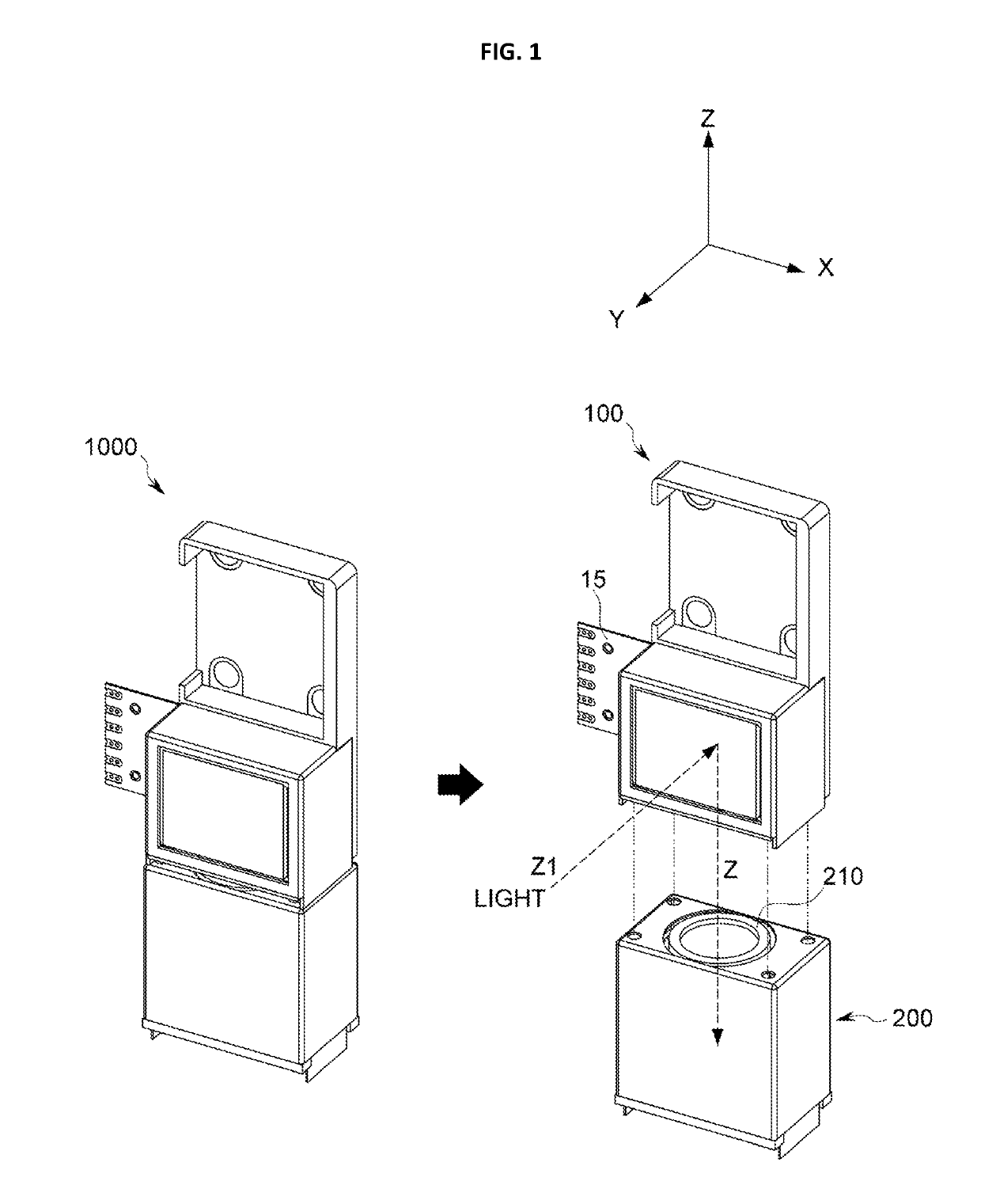
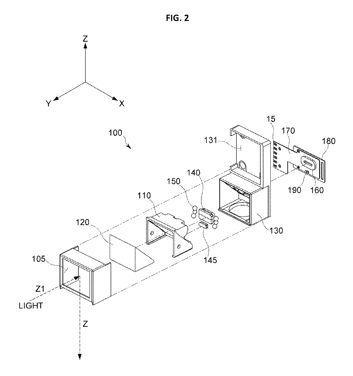
[0030]FIG. 1 is a diagram showing an overall configuration of an apparatus 100 for driving an optical-reflector (hereinafter, also referred to as a “driving apparatus”) according to an embodiment of the present disclosure and an actuator 1000 to which the driving apparatus is applied.

[0031]The driving apparatus 100 of the present disclosure may be implemented as a single device, or may also be implemented as a component of a single actuator 1000 so as to be coupled to an upper portion or like of a lens driving unit 200, which includes a lens (a zoom lens) 210, and a unit for performing auto focusing (AF) operation to the lens 210, a unit for performing optical image stabilization (OIS) in one axial direction, or a unit for performing AF operation and OIS operation together in one axis direction, as shown in FIG. 1.

[0032]In the present disclosure, light of a subject or the like is not directly input to the lens 210, but the light is input to the lens 210 after its path is changed (re...


PUM


Abstract

An apparatus for driving an optical-reflector includes a support frame having a groove line formed therein, an optical-reflector installed at the support frame to change a path of light input through an opening so that the light is put into a lens, a base frame having a guiding groove formed with a shape corresponding to the groove line, and a plurality of balls disposed between the groove line and the guiding groove so that the support frame and the base frame are kept in a spaced state, and a driving unit configured to move the support frame along a path corresponding to the groove line or the guiding groove.

Description

CROSS-REFERENCE TO RELATED APPLICATION AND CLAIM OF PRIORITY[0001]The present application claims priority to Korean Patent Application KR 10-2016-0128111 filed on Oct. 5, 2016 in the Korea Intellectual Property Office and Korean Patent Application KR 10-2017-0024368 filed on Feb. 23, 2017 in the Korea Intellectual Property Office, the disclosures of which are incorporated herein by reference.BACKGROUNDTechnical Field[0002]The present disclosure relates to an apparatus for driving an optical-reflector, and more particularly, to an apparatus for driving an optical-reflector for optical image stabilization (OIS), which improves precision of optical image stabilization by applying a structure for rotating an optical-reflector using a guide with a rounded shape or the like.Background Art[0003]Along with the development of hardware techniques and the change of user environments or the like, various and complicated functions are integrally implemented at a mobile terminal such as a smart p...

Claims


Application Information

Patent Timeline
Patent Type & Authority Patents(United States)
IPC IPC(8): G02B27/64H02P6/00H02K11/215H02K33/16
CPCG02B27/646H02P6/006H02K33/16H02K11/215G02B7/1821G06V40/10G06V10/145G06V10/147H04N23/685
Inventor YEON, JE SEUNGLEE, BYUNG CHEOLKANG, BYUNG KILLPARK, CHUL SOON
Owner JAHWA ELECTRONICS
Why Eureka
Try Eureka