EMU impulse antenna for low frequency radio waves using giant dielectric and ferrite materials

a technology of ferrite materials and impulse antennas, applied in the field of underwater structures, can solve the problems of reducing affecting the efficiency of emu impulse antennas, and difficulty in transferring a crisp high-current pulse from the power supply down a low-loss cable, so as to minimize reflection and loss in the system

Active Publication Date: 2019-07-02
SAUDI ARABIAN OIL CO
View PDF75 Cites 0 Cited by
  • Summary
  • Abstract
  • Description
  • Claims
  • Application Information

AI Technical Summary

Benefits of technology

This patent describes a system that combines energy storage, pulse formation, and radiating elements in a single structure to improve the efficiency and power of transmitting antennas. By eliminating the need for separate components, reflections and losses in the system are minimized. The system includes a fast-closing switch, such as a triggered spark gap, to initiate pulsed transmission. A large voltage is applied to bias the antennas apart and discharge in a single current pulse, resulting in a high power transient radio frequency signal. This design eliminates the problem of load matching between the power supply, cable, or transmission-line and the antenna, which can lead to reflections and losses in the system.

Problems solved by technology

The apparent ‘aperture’ of the antenna (wavelength to antenna size ratio) can be problematic.
Some current EM systems cannot easily match impedance of the system to the geological matrix for increasing transmission efficiency.
However, these systems have been shown to have difficulty transferring a crisp high-current pulse from the power supply down a low-loss cable, and then matching that pulse into the antenna.
In addition, the high-current cabling can also transmit a signal, which makes the resulting measurements unclear.

Method used


Image

  • EMU impulse antenna for low frequency radio waves using giant dielectric and ferrite materials
  • EMU impulse antenna for low frequency radio waves using giant dielectric and ferrite materials
  • EMU impulse antenna for low frequency radio waves using giant dielectric and ferrite materials

Examples


Embodiment Construction

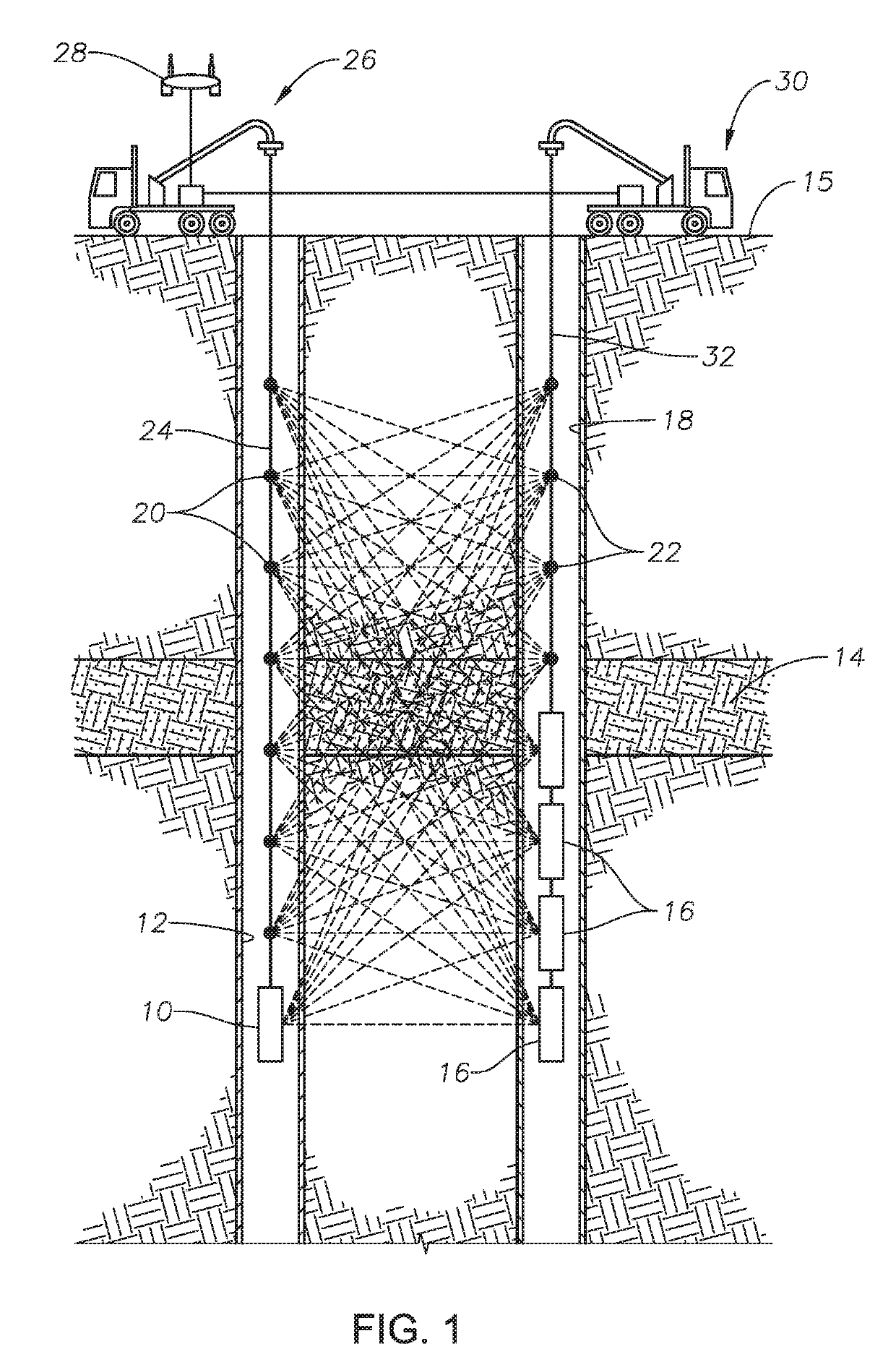
[0034]Looking at FIG. 1, an example arrangement of a transmitter-receiver array for a borehole to borehole electromagnetic survey is shown. The transmitter can be electromagnetic energy source 10. Electromagnetic energy source 10 can be located within well borehole 12. Well borehole 12 can extend through subsurface hydrocarbon reservoir 14. Electromagnetic energy source 10 can emit pulses of electromagnetic energy to travel through subsurface hydrocarbon reservoir 14 for electromagnetic imaging of subsurface hydrocarbon reservoir 14.

[0035]Although one electromagnetic energy source 10 is shown in the example of FIG. 1, in alternate embodiments, multiple electromagnetic energy sources 10 can be located within well borehole 12. Alternately, one or more electromagnetic energy sources 10 can be located at the earth surface 15 above the subsurface hydrocarbon reservoir. In the example of FIG. 1, a series of electromagnetic sensors 16 are located in sensor bore 18. Sensor bore 18 can be a ...


PUM

PropertyMeasurementUnit
voltageaaaaaaaaaa
currentaaaaaaaaaa
voltageaaaaaaaaaa

Abstract

An electromagnetic energy source for emitting pulses of electromagnetic energy includes a sonde assembly having a first section axially aligned with, and spaced from, a second section. An energy storage capacitor includes an electrode mounted in each of the first section and the second section of the sonde assembly and operable to generate an electric field. A capacitive charge storage medium is mounted in each of the first section and the second section of the sonde assembly and surrounds each electrode, where the capacitive charge storage medium is a giant dielectrics and giant permeability ferrite. A fast-closing switch is located between the first and second sections of the sonde assembly.

Description

CROSS REFERENCE TO RELATED APPLICATION[0001]This application is a continuation of, and claims priority to and the benefit of, co-pending U.S. application Ser. No. 15 / 820,944, filed Nov. 22, 2017, titled “EMU Impulse Antenna for Low Frequency Radio Waves Using Giant Dielectric and Ferrite Materials,” which is a continuation in part of, and claims priority to and the benefit of, co-pending U.S. application Ser. No. 15 / 458,772, filed Mar. 14, 2017, titled “EMU Impulse Antenna,” the full disclosure of each which is incorporated in this disclosure by reference in its entirety for all purposes.BACKGROUND1. Field of the Disclosure[0002]The present disclosure relates to imaging sub-surface structures, particularly hydrocarbon reservoirs and fluids within the hydrocarbon reservoirs, and more particularly to electromagnetic energy sources for electromagnetic surveying of sub-surface structures.2. Description of the Related Art[0003]Some electromagnetic (EM) surveying systems used in geophysic...

Claims


Application Information

Patent Timeline
Patent Type & Authority Patents(United States)
IPC IPC(8): G01D7/00G01V3/30G01V3/20G01V3/08
CPCG01V3/30G01V3/20G01V2003/084
Inventor ELLIS, ERIKASCHMIDT, HOWARD K.FELIX SERVIN, JESUS MANUEL
Owner SAUDI ARABIAN OIL CO
Why Eureka
Try Eureka