Connector

a technology of connecting rods and connectors, applied in the direction of coupling contact members, coupling device connections, lighting and heating apparatus, etc., can solve the problems of not being easily updated to smart network control, not taking a short time to achieve, and requiring exceedingly high costs

Active Publication Date: 2018-04-17
LITE ON ELECTRONICS (GUANGZHOU) LTD +1
View PDF6 Cites 0 Cited by
  • Summary
  • Abstract
  • Description
  • Claims
  • Application Information

AI Technical Summary

Benefits of technology

[0004]The invention provides a connector having an effect of transmitting a high frequency signal and compatible with current light fixtures (such as street lights).

Problems solved by technology

Currently, the connector of ANSI 136.41 specification only has 7 pins in total, and does not have spare pins providing for definition of a control means and transmission of a high frequency signal, resulting in existing street lights not being easily updated to smart network control.
If existing connectors of ANSI 136.41 specification were to be completely replaced, it would not take a short time to achieve and would require exceedingly high costs.

Method used


Image

  • Connector
  • Connector
  • Connector

Examples


Embodiment Construction

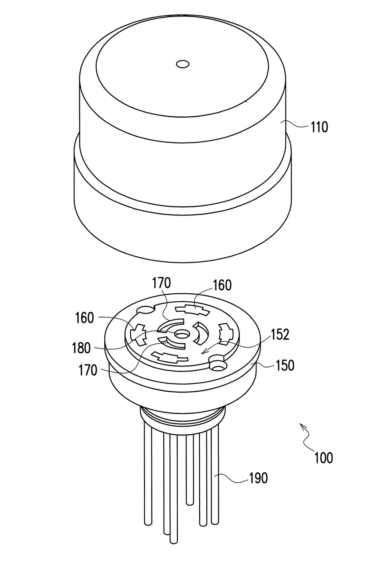
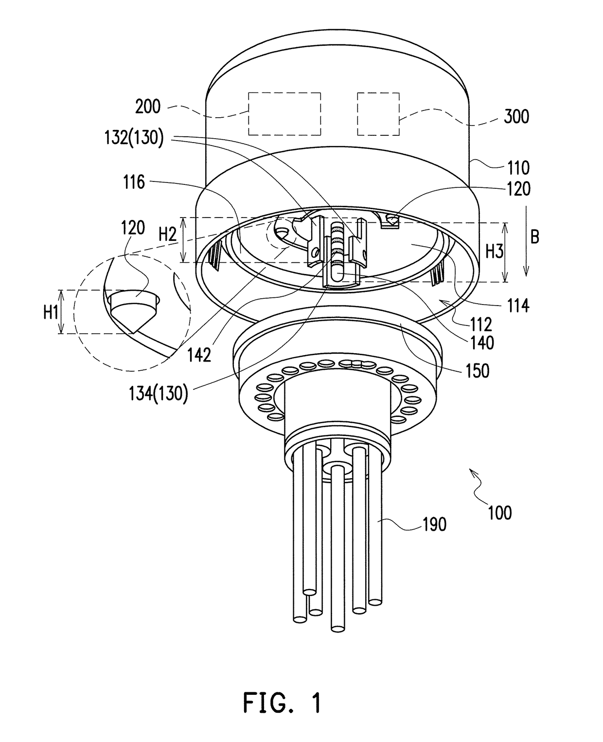
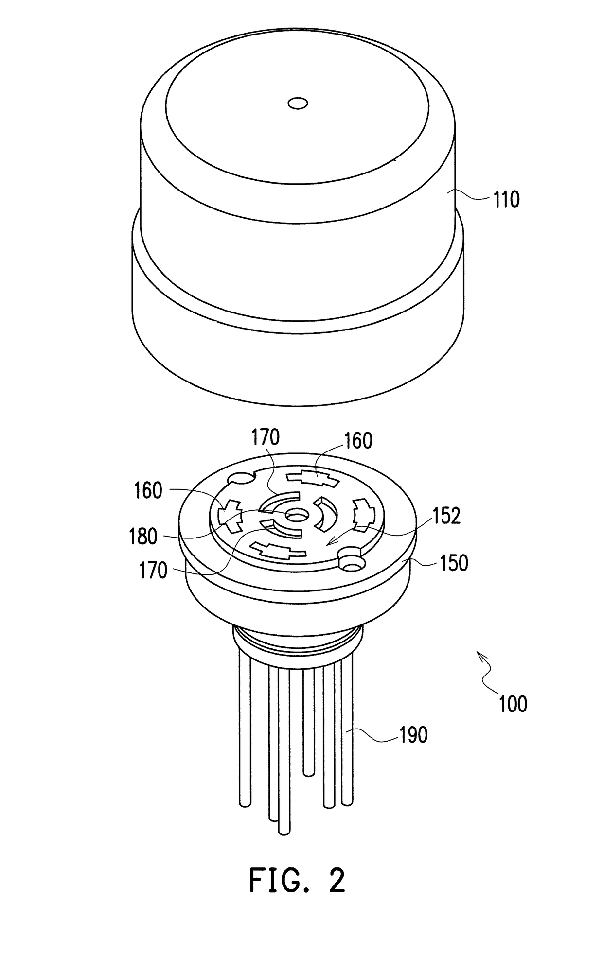
[0023]FIG. 1 illustrates a partial perspective exploded schematic diagram of a connector of an embodiment of the invention. FIG. 2 illustrates a partial perspective exploded schematic diagram of another angle of view of the connector of FIG. 1. FIG. 3 illustrates a bottom-view schematic diagram of an insulated housing of FIG. 1. FIG. 4 illustrates a top-view schematic diagram of a base of FIG. 1. FIG. 5 illustrates a connection schematic diagram of a plug and a spring sheet of FIG. 1. Referring first to FIG. 1 and FIG. 2, a connector 100 of the embodiment is suitable to be disposed on a lighting fixture (not illustrated), wherein the lighting fixture can be, for example, a street light, but is not limited thereto.

[0024]Referring simultaneously to FIG. 1, FIG. 2, and FIG. 3, the connector 100 of the embodiment includes an insulated housing 110, four connecting terminals 120, three pins 130, and a plug 140. The insulated housing 110 has a containing space 112 and a disposing surface 1...


PUM


Abstract

A connector includes an insulated housing, four connecting terminals, three pins and a plug. The insulated housing has a containing space and a disposing surface, and the disposing surface is located in the containing space. The connecting terminals are separately disposed in the containing space of the insulated housing and located on the disposing surface. The pins are separately disposed in the containing space of the insulated housing and extend from the disposing surface toward a direction away from the disposing surface, and the connecting terminals surround the pins. The plug is disposed in a center of the containing space of the insulated housing and located on the disposing surface. The plug is beneficial to rotate and has no directionality. The plug includes a plurality of conductive rings, the conductive rings are separately arranged along the direction away from the disposing surface, and the pins surround the plug.

Description

CROSS REFERENCE TO RELATED APPLICATION[0001]This application claims the priority benefit of China application serial no. 201720447668.X, filed on Apr. 26, 2017. The entirety of the above-mentioned patent application is hereby incorporated by reference herein and made a part of specification.BACKGROUND OF THE INVENTIONField of the Invention[0002]The invention relates to a connector, and more particularly relates to a connector applied to lighting fixtures.Description of Related Art[0003]Existing street lights (mainly in North America) mostly adopt a connector of NEMA 7 (ANSI 136.41) specification, connecting a control component to the connector of ANSI 136.41 specification, such that the control component connects to an internal circuit of the street light through the connector, so as to achieve a purpose of controlling the street light. Currently, the connector of ANSI 136.41 specification only has 7 pins in total, and does not have spare pins providing for definition of a control m...

Claims


Application Information

Patent Timeline
Patent Type & Authority Patents(United States)
IPC IPC(8): H01R9/05H01R24/20H01R13/11H01R24/58F21V23/06H01R13/66H01R107/00
CPCH01R24/58F21V23/06H01R13/111H01R13/6683H01R24/20H01R2107/00H01R2201/04H01R13/213H01R13/24H01R33/88
Inventor LEE, JOHNSONYEH, YAO-CHUNGHSU, CHIA-CHIH
Owner LITE ON ELECTRONICS (GUANGZHOU) LTD
Why Eureka
Try Eureka