Directional coupler

Active Publication Date: 2020-03-05
MURATA MFG CO LTD
View PDF0 Cites 0 Cited by
  • Summary
  • Abstract
  • Description
  • Claims
  • Application Information

AI Technical Summary

Benefits of technology

[0008]According to the present disclosure, it is possible to provide a directional coupler, whereas

Problems solved by technology

However, in the above-described directional coupler in the past, a plurality of filters in which pass ba

Method used


Image

  • Directional coupler
  • Directional coupler
  • Directional coupler

Examples


embodiment 1

1.1 Circuit Configuration of Directional Coupler

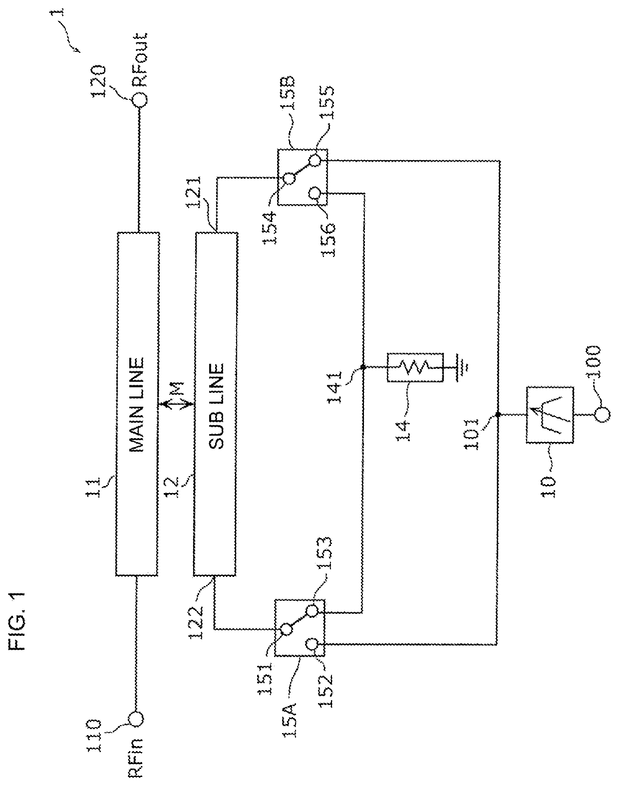
[0027]FIG. 1 is a circuit diagram illustrating an example of a functional configuration of a directional coupler 1 according to Embodiment 1. As illustrated in the figure, the directional coupler 1 includes a main line 11, a sub line 12, a variable filter 10, a termination circuit 14, and switches 15A and 15B. The main line 11 and the sub line 12 are electromagnetically coupled to each other as indicated by an arrow M in FIG. 1.

[0028]One end and another end of the main line 11 are connected to an input port 110 (RFin) and an output port 120 (RFout), respectively.

[0029]One end portion (first end portion) 121 of the sub line 12 is connected to the switch 15B, and another end portion (second end portion) 122 is connected to the switch 15A.

[0030]The termination circuit 14 is connected to the switches 15A and 15B.

[0031]The switch 15A includes a common terminal 151 (first common terminal), a selection terminal 152 (first selection terminal),...

embodiment 2

[0130]In the present embodiment, a configuration of a directional coupler 2 will be illustrated in which a variable termination circuit, a variable matching circuit, and a variable attenuator are further added to the directional coupler 1 according to Embodiment 1.

2.1 Circuit Configuration of Directional Coupler

[0131]FIG. 9 is a circuit diagram illustrating an example of a functional configuration of the directional coupler 2 according to Embodiment 2. As illustrated in the figure, the directional coupler 2 includes the main line 11, the sub line 12, the variable filter 10, variable termination circuits 14V and 16V, the switches 15A and 15B, a variable matching circuit 17V, a variable attenuator 18V, and a control unit 90. The main line 11 and the sub line 12 are electromagnetically coupled to each other as indicated by an arrow M in FIG. 9. The directional coupler 2 according to the present embodiment is different from the directional coupler 1 according to Embodiment 1 in that the...

third embodiment

[0146]In the present embodiment, compared to the directional coupler 1 according to Embodiment 1, the directional coupler 2 including a plurality of variable filters, and having a configuration for bypassing the variable filters will be described.

3.1 Circuit Configuration of Directional Coupler

[0147]FIG. 10 is a circuit diagram illustrating an example of a functional configuration of the directional coupler 3 according to Embodiment 3. As illustrated in the figure, the directional coupler 3 includes the main line 11, the sub line 12, variable filters 10A and 10B, the variable termination circuits 14V and 16V, the switches 15A, 15B, switches 19A, 19B, and the control unit 90. The main line 11 and the sub line 12 are electromagnetically coupled to each other as indicated by an arrow M in FIG. 9. The directional coupler 3 according to the present embodiment is different from the directional coupler 1 according to Embodiment 1 in that, the variable termination circuits 14V and 16V are a...


PUM


Abstract

A directional coupler includes a main line for transmitting a high frequency signal, a sub line electromagnetically coupled to the main line, a termination circuit for terminating one end portion of the sub line, and a variable filter that has an input terminal and an output terminal and the input terminal is connected to another end portion of the sub line. The variable filter is a filter unit circuit having one frequency band as a pass band or a stop band, and in the filter unit circuit, a variable passive element for shifting a frequency in the pass band or the stop band is disposed.

Description

[0001]This application claims priority from Japanese Patent Application No. 2018-163259 filed on Aug. 31, 2018. The content of this application is incorporated herein by reference in its entirety.BACKGROUND[0002]The present disclosure relates to a directional coupler.[0003]In the past, an electromagnetic coupler (directional coupler) in which a filter circuit composed of a plurality of filters and a plurality of switches is connected to one end portion (coupling port) of a sub line has been known (see, for example, U.S. Pat. No. 9,954,564).[0004]The plurality of switches selectively connect one filter of the plurality of filters to the sub line, and a high frequency signal in a desired frequency band can be detected without necessarily being interfered with a signal in other frequency bands.[0005]However, in the above-described directional coupler in the past, a plurality of filters in which pass bands are fixed is disposed, so that there is a problem that the directional coupler is...

Claims


Application Information

Patent Timeline
IPC IPC(8): H01P5/18H03F3/189H03H7/38H03H7/01H04B1/00H01P1/201
CPCH03F3/189H04B1/006H03H7/0115H01P1/201H03H7/38H01P5/187H01P5/18H03H7/0123H03H7/48H03H2210/036H03H2001/0078
Inventor SEKI, KENTAKIM, RYANGSUSHIMIZU, KATSUYA
Owner MURATA MFG CO LTD
Why Eureka
Try Eureka