RF Transceiver

a transceiver and rf technology, applied in the field of microwave rf circuits and analog electronic circuits, can solve problems such as bulky shells, achieve the effects of enhancing pass-band frequency signals, reducing coupling of adjacent microstrip lines, and avoiding power loss and radiation leakag

Inactive Publication Date: 2013-06-20
NAT CHUNG SHAN INST SCI & TECH
View PDF8 Cites 0 Cited by
  • Summary
  • Abstract
  • Description
  • Claims
  • Application Information

AI Technical Summary

Benefits of technology

[0008]It is another objective of the present invention to provide a RF transceiver for reducing coupling of adjacent microstrip lines to each other and radiation leakage from these lines in an impedance-matching manner by software according to the electromagnetic field theory.
[0009]It is another objective of the present invention to provide a RF transceiver for avoiding power loss and radiation leakage in transmission of data with a low-consumption circuit board and efficient microwave elements.
[0010]To achieve the foregoing objectives, the RF transceiver includes a voltage-controlled oscillator, a power divider, a low-pass filter, a low-noise amplifier and a mixer. The voltage-controlled oscillator receives a signal from the modulator and accordingly generates a frequency modulated continuous wave signal. The power divider receives the frequency modulated continuous wave signal from the voltage-controlled oscillator. The low-pass filter receives the frequency modulated continuous wave signal from the power divider, reduces high order harmonic frequency signals, enhances pass-band frequency signals, and transmits the dominant frequency signal within the pass-band to an RF antenna. The low-noise amplifier receives, amplifies and transfers an echo signal of target. The mixer combines the continuous oscillation frequency signal from the power divider with the echo signal of target from the low-noise amplifier so that the two signals are added up or subtracted from each other in a frequency band.

Problems solved by technology

However, cavity mode interference must be taken into consideration in the use of the conventional RF transceiver.
However, the isolation chambers entail a bulky shell to contain the RF transceiver.

Method used


Image

  • RF Transceiver
  • RF Transceiver
  • RF Transceiver

Examples


Embodiment Construction

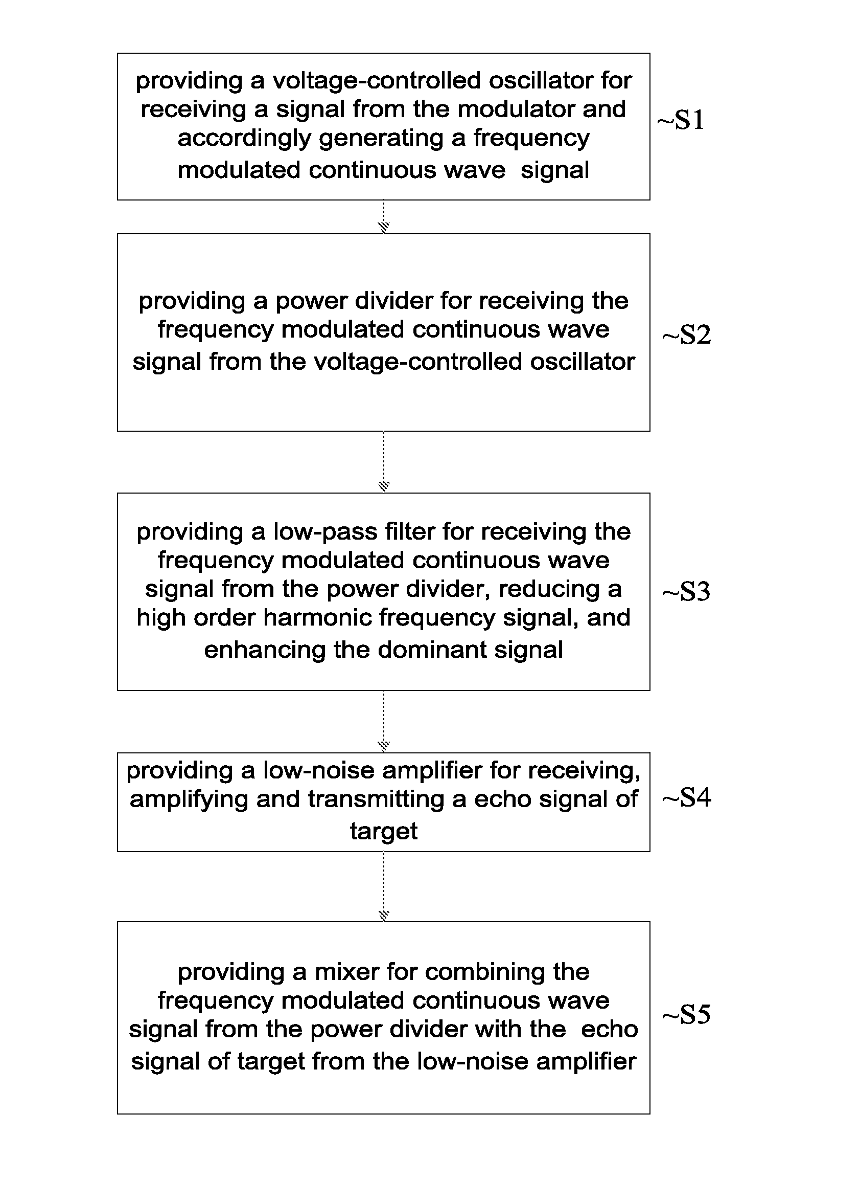
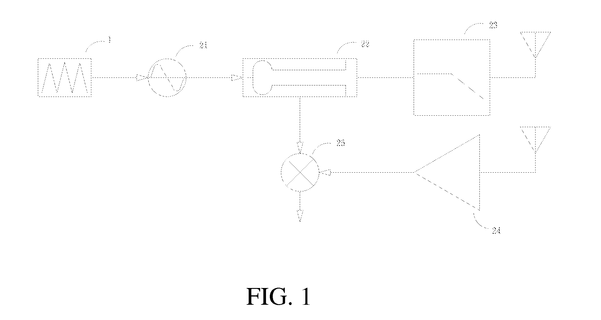
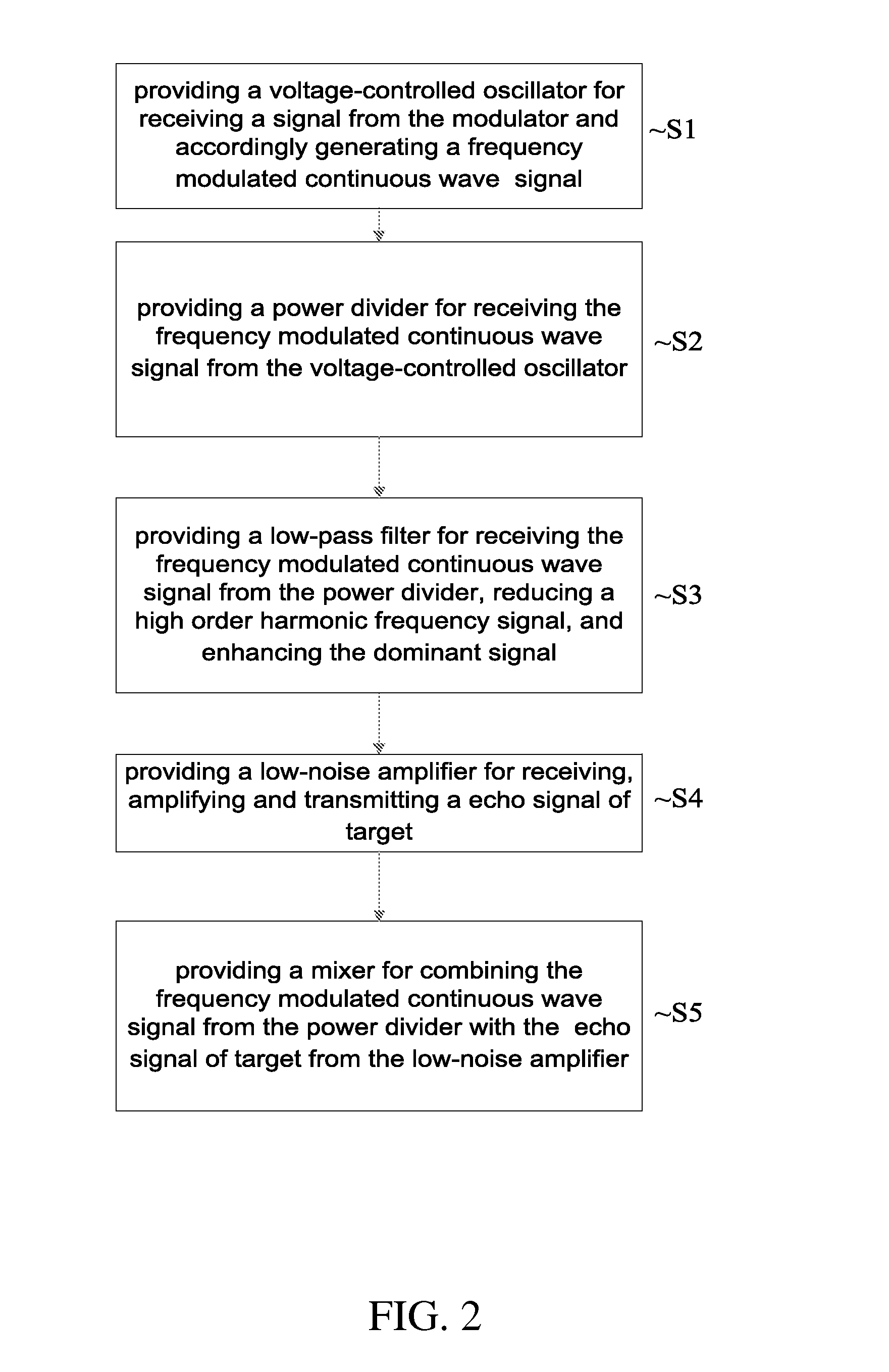
[0015]Referring to FIG. 1, there is shown an RF transceiver for use in a signal generation and transmission system according to the preferred embodiment of the present invention. The signal generation and transmission system includes a modulator 1 for controlling a voltage.

[0016]The RF transceiver includes a voltage-controlled oscillator 21, a power divider 22, a low-pass filter 23, a low-noise amplifier 24 and a mixer 25. The voltage-controlled oscillator 21 is connected to the modulator 1. The voltage-controlled oscillator 21 is used to receive a signal from the modulator 1 and produce a frequency modulated continuous wave signal accordingly.

[0017]The power divider 22 is connected to the low-pass filter 23 at an output end and connected to the mixer 25 at another output end. Based on different impedances at the output ends, the power divider 22 sends the frequency modulated continuous wave signal to the low-pass filter 23 and to a local oscillation end of the mixer 25. The power d...


PUM


Abstract

A signal generation and transmission system includes a modulator and an RF transceiver. The RF transceiver includes a voltage-controlled oscillator, a power divider, a low-pass filter, a low-noise amplifier and a mixer. The voltage-controlled oscillator receives a signal from the modulator and produces a frequency modulated continuous wave signal. The power divider receives the frequency modulated continuous wave signal from the voltage-controlled oscillator. The low-pass filter receives the frequency modulated continuous wave signal from the power divider. The low-noise amplifier receives, amplifies and transfers a target echo signal. The mixer combines the frequency modulated continuous wave signal from the power divider with the echo signal of target from the low-noise amplifier so that the two signals are added up or subtracted from each other in a frequency band.

Description

BACKGROUND OF INVENTION[0001]1. Field of Invention[0002]The present invention relates to a microwave RF circuit and analog electronic circuit and, more particularly, to a RF transceiver for reducing noises.[0003]2. Related Prior Art[0004]A conventional RF transceiver includes an antenna, an RF filter, a two-way switch, a receiver and a transmitter. The two-way switch connects the antenna to the receiver or transmitter. The RF transceiver converts signal to an RF from a baseband. The frequency range of the baseband is about DC to tens of MHz. The frequency range of the RF is in the order of a GHz.[0005]To avoid a signal from interfering with another, conversion of the RF to the baseband signal and the conversion of the baseband signal to the RF are done at a single mixing step. Thus, the RF is amplified in the receiver. A mixer mixes the RF signal with a local oscillation signal to provide a converted signal that includes a baseband component. However, cavity mode interference must b...

Claims


Application Information

Patent Timeline
Patent Type & Authority Applications(United States)
IPC IPC(8): H04B1/44
CPCG01S7/35
Inventor CHANG, CHI-HOHUANG, JUI-CHICHEN, JAU-CHENLEE, KUEI-JUTSENG, CHI-HUA
Owner NAT CHUNG SHAN INST SCI & TECH
Why Eureka
Try Eureka