Monolithic mode stripping fiber ferrule/collimator and method of making same

a fiber ferrule and monolithic mode technology, applied in the field of optical energy transmission technology, can solve problems such as diffuse scattering, and achieve the effects of reducing the coupling of any reflection, reducing loss, and increasing the optical damage limit of this termination

Active Publication Date: 2007-12-11
ELECTRO OPTICS TEVCHNOLOGY
View PDF15 Cites 116 Cited by
  • Summary
  • Abstract
  • Description
  • Claims
  • Application Information

AI Technical Summary

Benefits of technology

[0020]According to the invention, a monolithic ferrule / endcap / optical fiber structure is provided wherein an optical fiber is terminated in a ferrule and bonded by fusion to form a monolithic unit which minimizes optical loss and is typically capable of transmitting high power laser radiation, preferably on the order of 500 W and higher, without damage to the optical fiber and ferrule.
[0022]Polishing and anti-reflection coating the end-face of this monolithic structure allows radiation to be coupled into and out of the optical fiber core with low loss. As the endcap design diameter is increased, the beam size of this radiation on the end-face of the ferrule structure also increases, thereby increasing the optical damage limit of this termination and reducing coupling of any reflection back into the core of the optical fiber (i.e., “Return Loss”). If additional reduction of Return Loss is desired the end-face of the monolithic ferrule structure may be angle polished as required. In order to prevent cladding modes from burning the optical fiber protective polymer coating during high power operation, the coating needs to be stripped within the ferrule structure, which leaves a void between the inner diameter of the ferrule and the outer diameter of the fiber. According to the invention, this void is filled by placing in the ferrule a powder that has a higher refractive index than that of the fiber cladding. The powder is also chosen to have a similar thermal expansion coefficient, but a lower softening temperature, than the ferrule material. The powder may be melted with a localized heat source, such as a laser, to increase optical contact with the optical fiber and ferrule. Bubbles / voids will result in the melted powder regions which cause diffuse scattering of the mode stripped cladding modes. The ferrule length is required to be long enough to ensure that all cladding mode energy ultimately diverges to the cladding of the optical fiber such that it can then be removed by the melted powder mode stripping region. Radiation scattered in the mode stripping region or entering the ferrule directly that has a high angle of incidence on the outer diameter surface of the ferrule will be totally reflected at this surface and guided along the ferrule length. In accordance with the invention, this radiation is reflected out of the ferrule structure at the optical fiber end through a flaring at the end of the ferrule and interaction with a reflective coating applied to the surface of the flaring. With substantially all cladding mode radiation removed, a transmissive adhesive is provided that strain relieves the optical fiber and a transmissive polymer adhesive / coating is applied, recoating any uncoated optical fiber at the flared end of the ferrule structure. Radiation which is not launched into the fiber core is thereby either scattered or reflected away from the monolithic ferrule structure, where it can be absorbed by heat dissipative and conductive materials, such as metal acting as a heat sink.
[0023]According to another aspect of the invention, a laser is used as a tool to form a lens directly onto the end of the monolithic ferrule structure to achieve a substantially collimated beam out of the ferrule structure thereby forming a monolithic fiber collimator. To facilitate the formation of the endcap lens of desired size and shape, the ferrule diameter, the length of the protruding endcap prior to fusion / melt back, and the size / shape of the laser radiation focused on the endcap are selected as required. Careful control of the focused laser size, shape and time varied power in relation to the ferrule diameter and endcap protrusion length determines the form of an aspherical lens. Alternatively, or additionally, a sharply focused laser can be scanned across the ferrule end to facilitate the formation of an aspherical lens surface. To form a lens of the desired focal length, a mirror that is transmissive to the melting laser (e.g. a CO2 laser) is disposed at the desired collimator waist location. Radiation suited to the fiber application is launched down the optical fiber. Reflected power of this particular radiation from the mirror at the desired waist location is monitored with a tap in the optical fiber as the melting laser radiation is applied. When the optimal lens has been formed the melting laser is turned off. In a similar manner, other desired lens powers can be formed for non-collimated beams.
[0026]Another application of the invention is use with double clad fiber, where the double clad optical fiber is used to confine cladding modes of the inner cladding and prevent them from burning the fiber polymer protective coating. This configuration requires that any radiation not coupled into the core be confined to the inner cladding region only. Because the outer cladding confines inner cladding modes, the double clad fiber can be made as long as desired, allowing for an inner cladding mode stripping ferrule according to the invention to be located remote from the fiber termination. This can be particularly useful for very high power if water-cooling of the mode-stripping ferrule is impractical or undesirable at the fiber termination. The endcap and double clad fiber can be the same diameter, and the termination ferrule / collimator structure can be relatively short, since the mode stripping occurs in the remote mode stripping ferrule. “Jacketed air clad fiber” and photonic crystal fiber can also be used in place of conventional double clad fiber. In such cases, the single core fiber may be large mode area fiber—with a mode field diameter consistent with these fiber types.

Problems solved by technology

Bubbles / voids will result in the melted powder regions which cause diffuse scattering of the mode stripped cladding modes.

Method used


Image

  • Monolithic mode stripping fiber ferrule/collimator and method of making same
  • Monolithic mode stripping fiber ferrule/collimator and method of making same
  • Monolithic mode stripping fiber ferrule/collimator and method of making same

Examples


Embodiment Construction

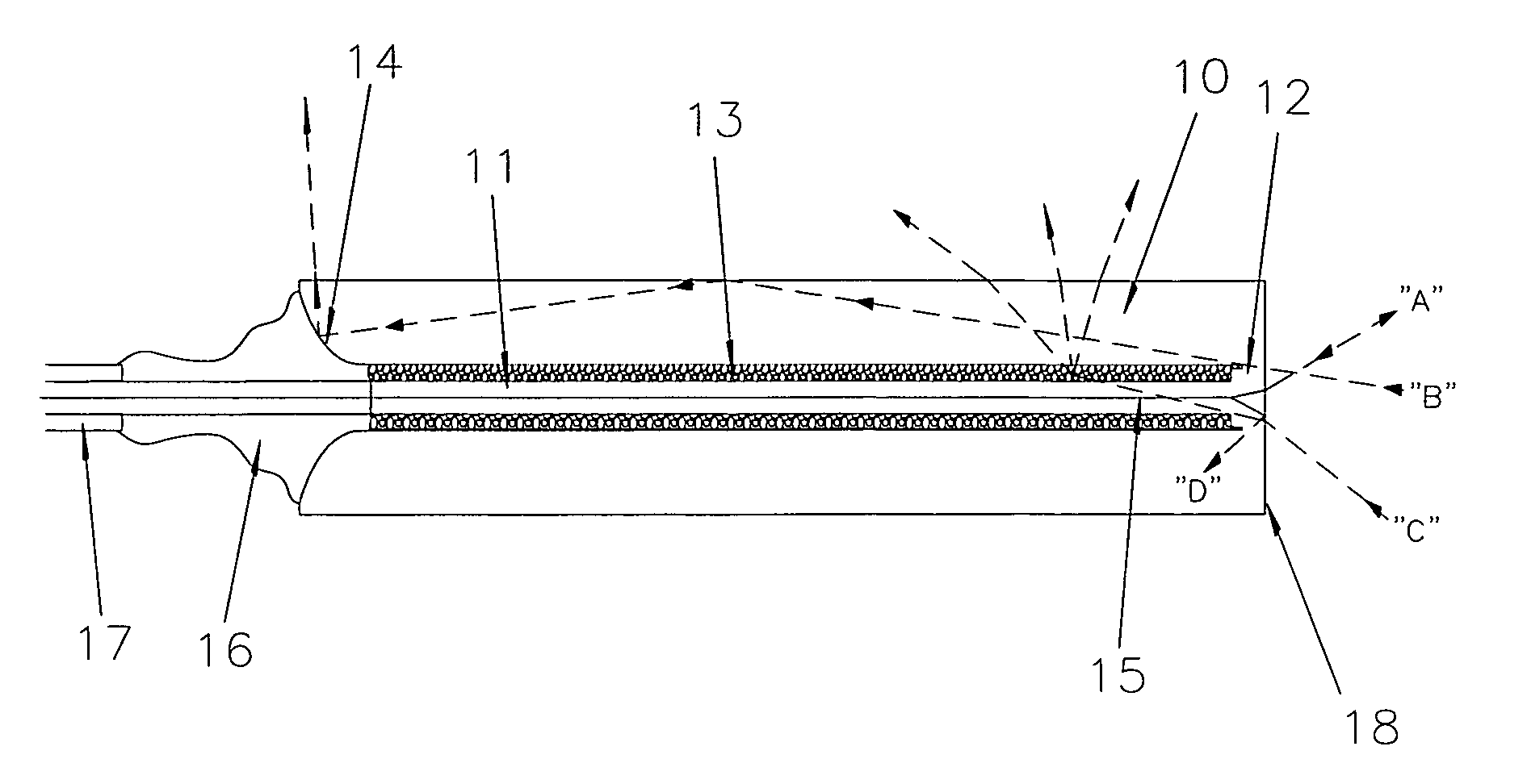
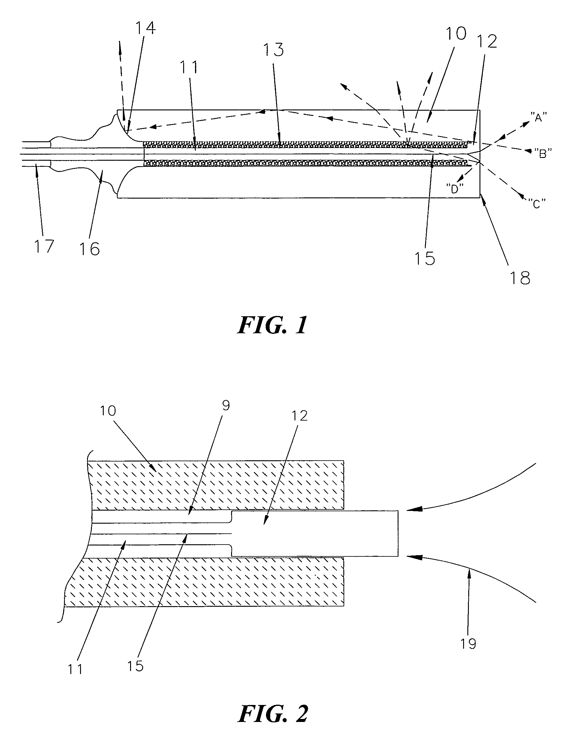
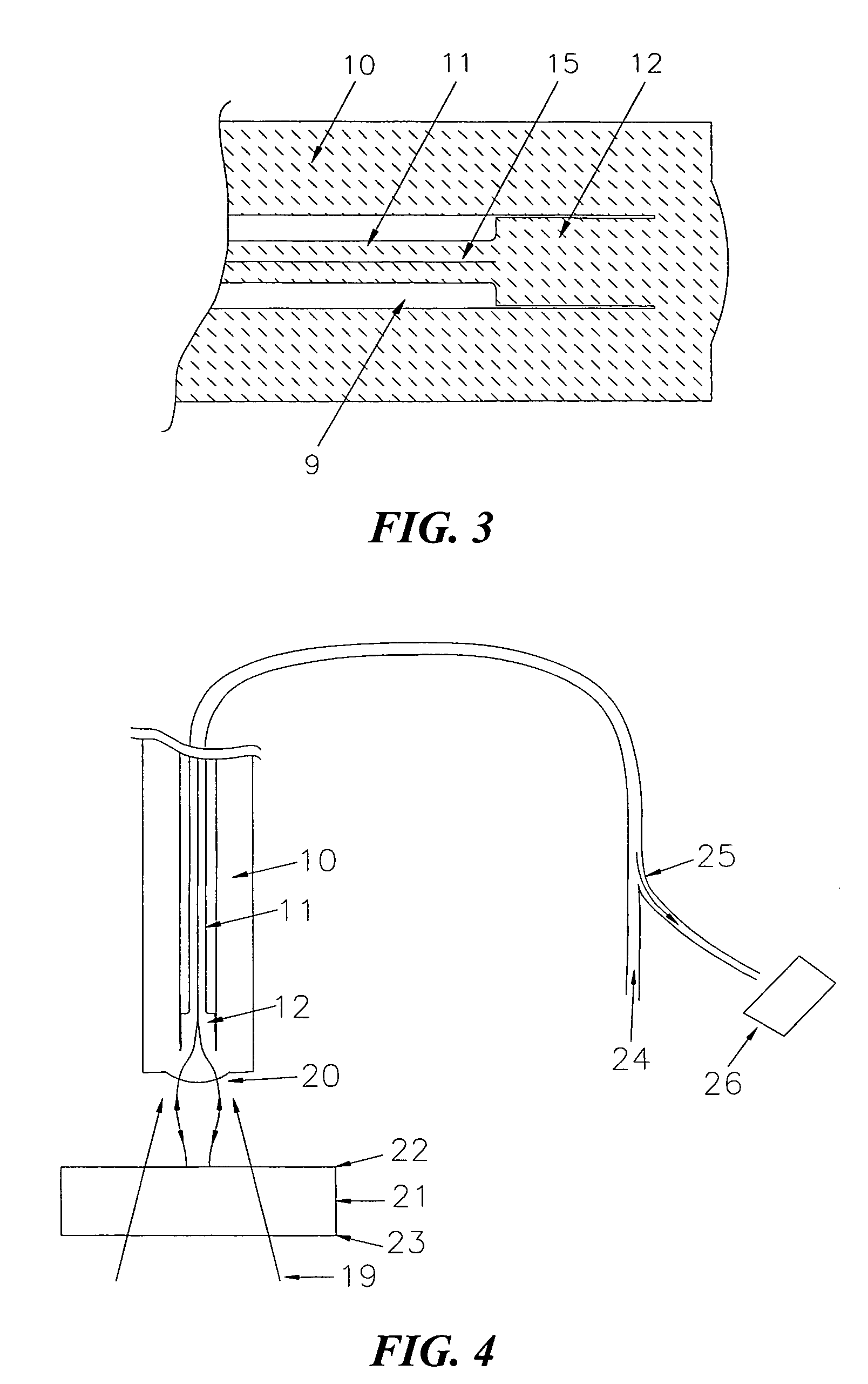
[0036]Referring to FIG. 1, one embodiment of the invention is illustrated in a cross-sectional diagram. A fiber optic junction is provided by the combination of a fused silica ferrule 10 that has an inner diameter fabricated to a high tolerance to just accept a fused silica coreless fiber stub “endcap”12 (FIG. 2, not to scale) centered within the ferrule 10, and a stripped silica optical fiber 11 with core 15 that is disposed within the ferrule 10 and fused to the endcap 12. By coreless, it is understood to mean a substantially homogeneous element such as a glass fiber that has not been prepared with a core material of fiber. By stripped, it is understood that the polymer coating 17 or jacket has been removed from the outer surface of the fiber in the stripped region. The outer diameter of the stripped region of the optical fiber 11 is sufficiently less than the inner diameter of the ferrule 10 to allow an appropriately fine silica glass powder 13 to occupy and fill the space betwee...


PUM

PropertyMeasurementUnit
diameteraaaaaaaaaa
diameteraaaaaaaaaa
diameteraaaaaaaaaa

Abstract

A monolithic ferrule / endcap / optical fiber structure is provided wherein an optical fiber is terminated in a ferrule and bonded by fusion to form a monolithic unit which minimizes optical loss and is typically capable of transmitting high power laser radiation, preferably on the order of 500 W and higher, without damage to the optical fiber and ferrule. Ferrule, endcap, optical fiber and fusible powder are composed of material of substantially the same physical characteristics such that, when all are fused together, the structure so formed is monolithic and the optical path is transparent.

Description

CROSS-REFERENCES TO RELATED APPLICATIONS[0001]NOT APPLICABLESTATEMENT AS TO RIGHTS TO INVENTIONS MADE UNDER FEDERALLY SPONSORED RESEARCH AND DEVELOPMENT[0002]NOT APPLICABLEREFERENCE TO A “SEQUENCE LISTING,” A TABLE, OR A COMPUTER PROGRAM LISTING APPENDIX SUBMITTED ON A COMPACT DISK[0003]NOT APPLICABLEBACKGROUND OF THE INVENTION[0004]This invention relates to optical energy transmission technology and more particularly to fiber ferrules suitable for terminating optical fibers and mode stripping as may be useful with high power laser radiation transmission. The invention further relates to lensed fibers and collimators. Moreover, the invention also concerns methods of manufacturing such ferrules and lenses.[0005]The flexibility and light weight of fiber optic cables make them well suited for delivery of high power laser beams in applications such as robotics. Since they can be readily fused in an interface to the output of high power fiber lasers, fiber optic cables are also useful fo...

Claims


Application Information

Patent Timeline
Patent Type & Authority Patents(United States)
IPC IPC(8): G02B6/36
CPCG02B6/4296
Inventor SCERBAK, DAVID GERALDGOTTFRIED, GORDON EDGARPOOLER, ERIC SEANROGERS, EVAN MATTHEW
Owner ELECTRO OPTICS TEVCHNOLOGY
Why Eureka
Try Eureka