Color display device using dichroic filter

a color display device and dichroic filter technology, applied in the field of color display devices, can solve the problems of reducing operational reliability, affecting the speed of scanning, so as to achieve the effect of minimizing optical loss

Inactive Publication Date: 2007-05-08
SAMSUNG ELECTRO MECHANICS CO LTD
View PDF1 Cites 3 Cited by
  • Summary
  • Abstract
  • Description
  • Claims
  • Application Information

AI Technical Summary

Benefits of technology

[0024]Accordingly, the present invention has been made keeping in mind the above problems occurring in the prior art, and an object of the present invention is to provide a color display device, which minimizes optical loss occurring when diffracted light beams are produced by diffractive light modulators, and which uses a dichroic filter to select diffracted light beams having desired orders from among a plurality of diffracted light beams having a plurality of orders.

Problems solved by technology

It is difficult for the above-described laser scanning type light beam scanning apparatus to achieve high-speed printing, due to the low switching speed of the laser diode 10 and the speed problem of the polygon mirror 13.
However, the high-speed motor is expensive, and the motor operating at high speed generates heat, vibration and noise, thus degrading operational reliability, so that a significant improvement in scanning speed cannot be expected.
Meanwhile, the rotational speed of the optical reflector and the image clock cannot comply with the large number of optical scans.
However, the surface emitting laser has a problem in that an output light beam has an unstable polarization direction.
Further, the difference in intensity results in irregular pitch in an image, thus considerably degrading image quality.

Method used


Image

  • Color display device using dichroic filter
  • Color display device using dichroic filter
  • Color display device using dichroic filter

Examples


Embodiment Construction

[0037]The construction of a color display device using a dichroic slit according to the present invention is described in detail with reference to the drawings below.

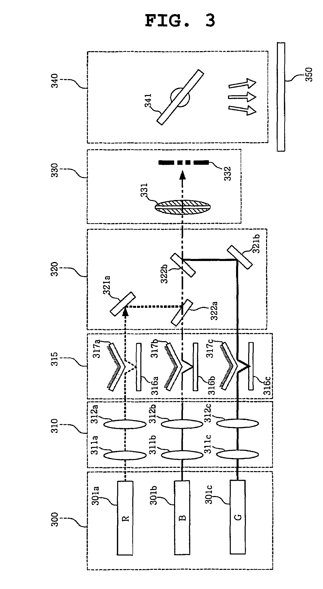
[0038]FIG. 3 is a diagram showing the construction of a color display device using a dichroic slit according to an embodiment of the present invention.

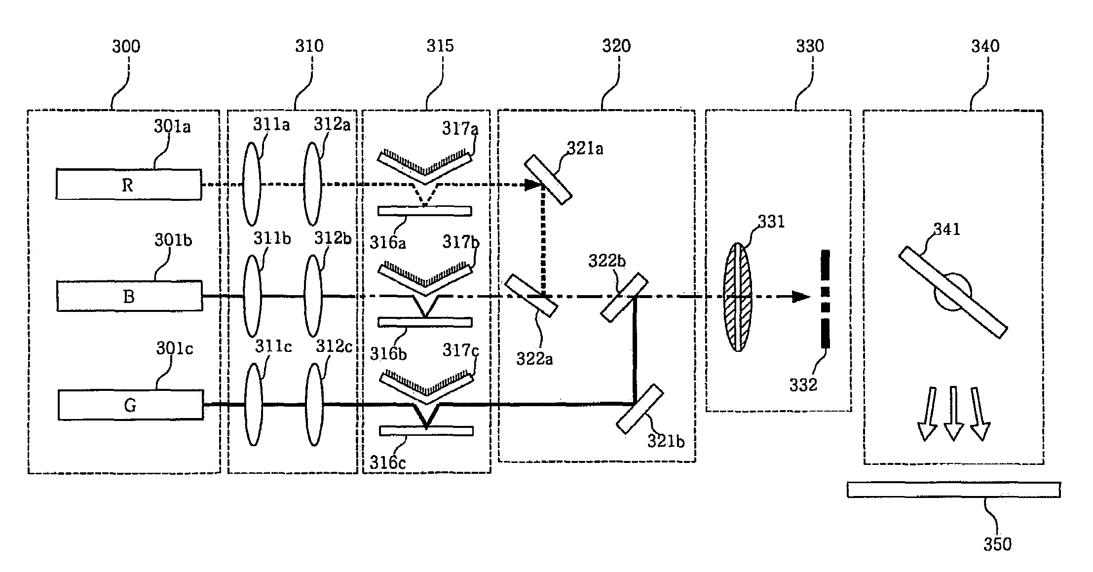
[0039]Referring to FIG. 3, the color display device using the dichroic slit according to the embodiment of the present invention includes a plurality of light sources 300, an illumination lens system 310, a diffractive light modulation system 315, a combining system 320, a Fourier filter system 330, a projection system 340, and a screen 350.

[0040]The plurality of light sources 300 is composed of, for example, a red light source 301a, a blue light source 301b and a green light source 301c. The plurality of light sources 300 may be light sources that are formed of semiconductor devices such as LEDs or Laser Diodes (LDs). Such semiconductor light sources have many characteri...


PUM


Abstract

A color display device is disclosed. The color display device includes an illumination lens system, a diffractive light modulation system, a combining system, a Fourier filter system, and a projection system. The illumination lens system converts a plurality of light beams into linear parallel light beams. The diffractive light modulation system produces a plurality of diffracted light beams having a plurality of diffraction orders by modulating each of the plurality of parallel light beams that are almost perpendicularly incident from the illumination lens system, The combining system focuses the plurality of diffracted light beams having the plurality of diffraction orders. The Fourier filter system selects diffracted light beams having desired diffraction orders using a dichroic filter. The projection system focuses the diffracted light beams on an object, and allowing the focused diffracted light beams to scan the object.

Description

BACKGROUND OF THE INVENTION[0001]1. Field of the Invention[0002]The present invention relates generally to a color display device and, more particularly, to a color display device, which improves diffraction efficiency by causing light to be almost perpendicularly incident on diffractive light modulators, and which uses a dichroic filter to select diffracted light beams having desired orders from among a plurality of diffracted light beams having a plurality of orders.[0003]2. Description of the Related Art[0004]A light beam scanning apparatus is an apparatus for producing an image by causing a light beam to form spots on a photosensitive medium through scanning in an image forming apparatus such as a laser printer, a display device, a Light Emitting Diode (LED) printer, an electrophoto copying machine or a word processor.[0005]As image forming apparatuses develop toward compactness, high speed and high resolution, light beam scanning apparatuses have been accordingly researched and...

Claims


Application Information

Patent Timeline
Patent Type & Authority Patents(United States)
IPC IPC(8): G03B21/26G02B27/10G02B27/42G02B5/18G03B21/14
CPCG03B21/14G03B33/12G03B21/142G03B21/2066G03B21/208H04N9/3105
Inventor YANG, HAENG SEOKSHIN, DONG HOOH, KWAN YOUNGAN, JUN WONYUN, SANG KYEONG
Owner SAMSUNG ELECTRO MECHANICS CO LTD
Why Eureka
Try Eureka