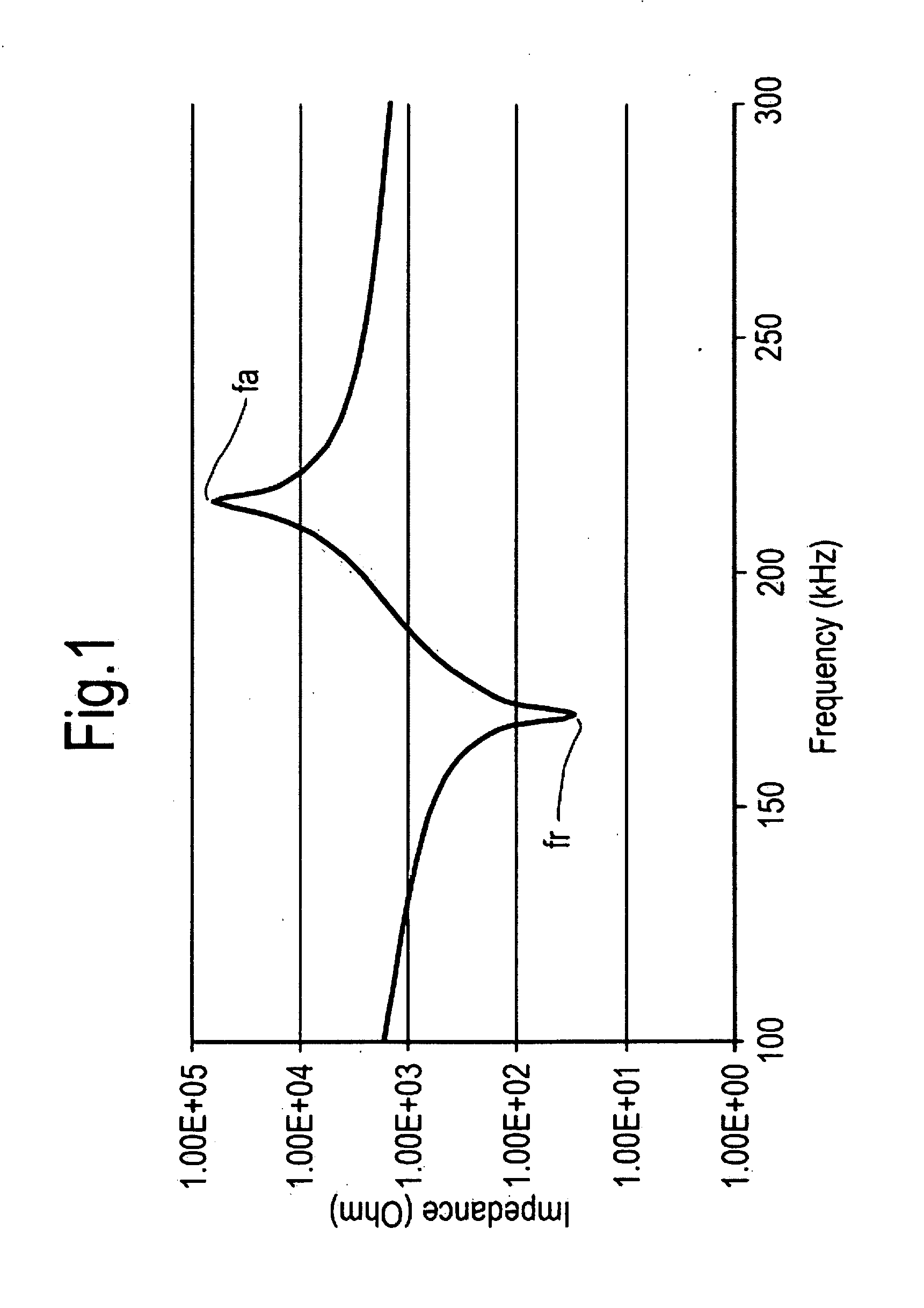
[0028]The present application has realised that by having a vibrator body for generating and / or receiving acoustic or ultrasonic waves (such as a piezoelectric material or a magnetostrictive material or a electrostrictive material) having a first anti-
resonance frequency and a second anti-
resonance frequency such that the first anti-
resonance frequency is substantially an odd multiple of the second anti-resonance frequency, a single matching layer can be used to match the
acoustic impedance of the vibrator body into the medium. The different anti-resonance frequencies can be provided by the vibrator body comprising multiple parts for generating and / or receiving acoustic or ultrasonic waves each part having its own characteristic anti-resonance / resonance frequency or provided by the same part for generating and / or receiving acoustic or ultrasonic waves forming the vibrator body (i.e. the vibrator body comprises a part). By having a matching layer having an
acoustic impedance which can be made to acoustically match a vibrator body for generating and / or receiving acoustic or ultrasonic waves having multiple anti-resonant / resonant frequencies, the present invention allows the selection of multiple anti-resonant / resonant frequencies provided by the vibrator body within a single volume of the transducer.
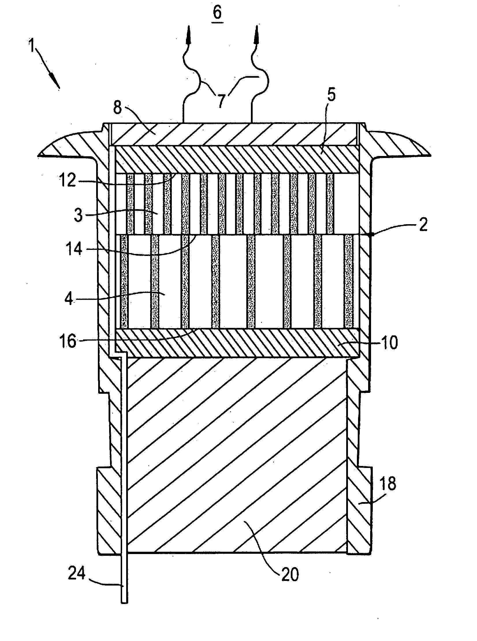
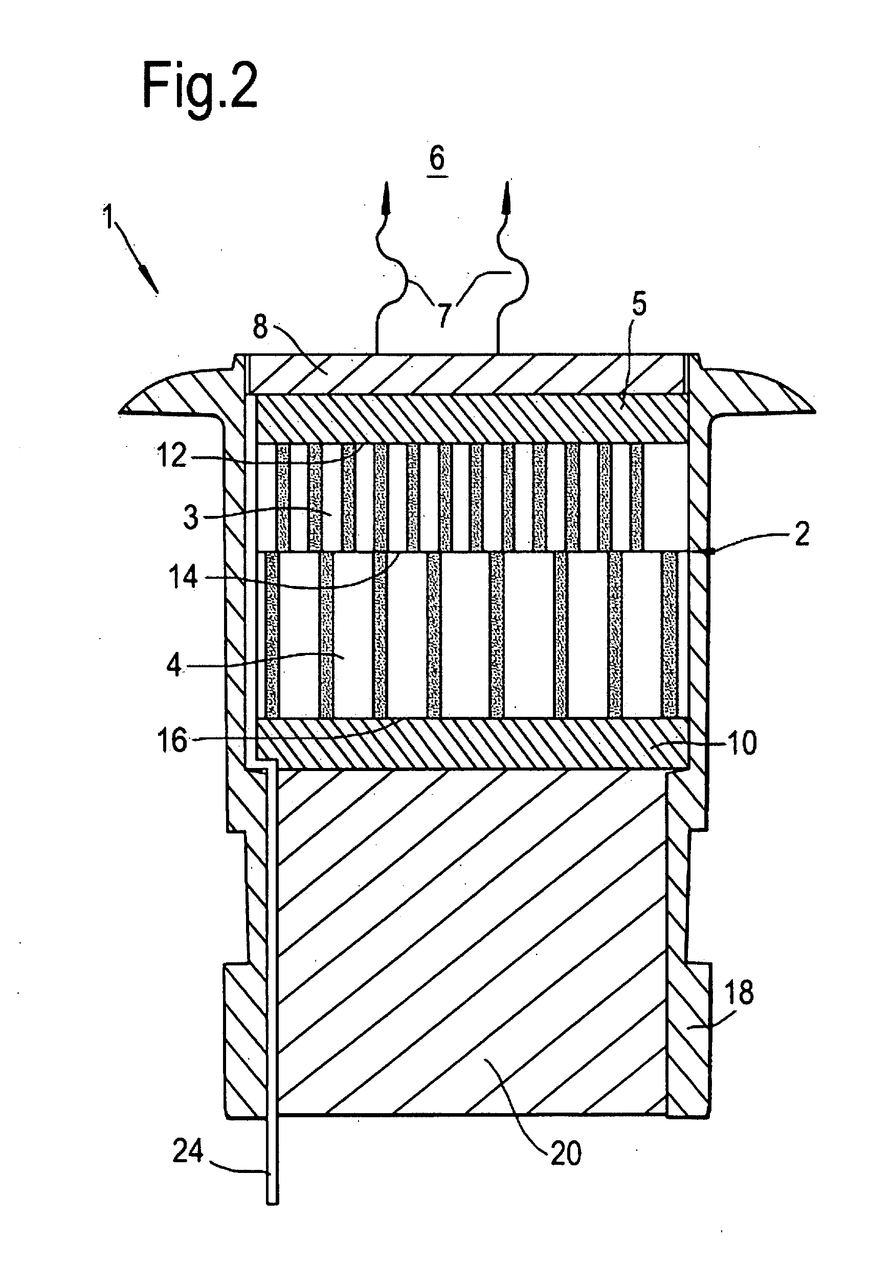
[0039]Materials for generating and / or receiving ultrasonic or acoustic waves such as piezoelectric materials vibrate in two or more planes, often a thickness and a
radial plane. Preferably, the vibrator body comprises a composite comprising a material for generating and / or receiving ultrasonic or acoustic waves and a passive material. By forming the vibrator body or anyone one of the parts (first or second part) forming the vibrator body into a composite, the lateral mode is suppressed and the performance in the thickness direction significantly improves. In the present invention, a passive material is a material that does not generate ultrasonic / acoustic waves, e.g. a
polymer. There are various techniques in the art to manufacture a
composite structure. For example, where the material for generating and / or receiving ultrasonic / acoustic waves is a piezoelectric material, the technique involves but not limited to suitably arranging piezoelectric rods in a
polymer and then
slicing off disks perpendicular to the rods (otherwise known as piezocomposites). Other techniques include the ‘dice and fill technique’ whereby deep grooves are
cut out in the piezoelectric
ceramic and either a
polymer (
epoxy,
polyurethane, syntactic polymer,
thermoplastic) is cast into the grooves or left as air filled voids (“The Role of Piezocomposites in Ultrasonic Transducers” by Wallace Arden Smith, IEEE Proceedings of the Ultrasonic Symposium, 1989, pp. 755-766). For example, in the case of the first arrangement of the vibrator body, the first and / or second part for transmitting and receiving ultrasonic / acoustic waves is / are a first and / or second piezocomposite comprising a piezoelectric material for transmitting and receiving ultrasonic / acoustic waves and a passive material. In the case of the second arrangement of the vibrator body, then the part forming the vibrator body can simply be a piezocomposite which is driven to provide different
modes of vibration along the radial or lateral or thickness or width of the piezocomposite depending upon its geometric shape.
[0041]The
advantage in using composite materials as opposed to conventional bulk materials for generating and / or receiving ultrasonic / acoustic waves is the flexibility by which the
acoustic impedance and resonant frequency can be controlled / tailored to match the medium under investigation, e.g. water. Typically, forming the material into a composite as opposed to the bulk material has a tendency to shift the resonant frequency of the material downward. Other advantages of the use of composites include improved frequency bandwidth, reduced lobes, increase reception sensitivity and reduced cross
coupling in arrays. However, fundamentally this has been achieved by suppressing one of the frequency
modes of operation meaning the longer range option (
low frequency range) is sacrificed, the higher resolution option (
high frequency range) is sacrificed or there is compromise between the two.
[0043]As the resonant frequency of the
composite material for generating and / or receiving ultrasonic / acoustic waves varies with the geometry of the material, the geometry of the
composite material can be tailored so that in the first arrangement of the vibration body the first part and when combined with the second part in a single volume can be effectively matched into the medium. Likewise in the second arrangement of the vibrator body, the geometry of the
composite material can be tailored so that a part forming the vibrator body can be effectively matched into the medium. Whilst the frequency at which it resonates varies with the shape or size of the composite material (e.g. thickness) according to equation 8, the acoustic impedance of the composite material can be varied by varying the density of the composite material which in turn is dependent upon the relative proportion of the material for generating and / or receiving ultrasonic / acoustic waves to the passive material. Thus by varying the thickness of the vibrator body in combination to their composition (density), the present applicant can tailor the vibrator body so that the quarter
wavelength thickness of the matching layer associated with the first part is substantially an odd multiple of the quarter
wavelength thickness of the matching layer associated with the first part coupled to the second part. Likewise, in the second arrangement of the vibrator body, the vibrator body can be tailored so that the quarter
wavelength thickness of the matching layer associated with the first vibration mode of the part forming the vibrator body is substantially an odd multiple of the quarter wavelength thickness of the matching layer associated with the second mode of vibration of that vibrator body.
[0046]In a second embodiment of the present invention, the vibrator body is similarly arranged as in the first arrangement of the first embodiment of present invention whereby the vibrator body comprises a first part for generating and / or receiving ultrasonic or acoustic waves acoustically coupled to a second part for generating and / or receiving ultrasonic or acoustic waves. However, the vibrator body is arranged so that the geometry of the first and the second part can be tailored so that the first part provides an additional matching layer for matching the second part to the medium. By utilising the first part as an additional matching layer for the second part and by making the second part to operate over a relatively
low frequency, i.e. 50 kHz to 100 kHz, the transducer according to the present invention can be tailored to operate over a
low frequency band. Preferably, the first part can be made a matching layer of the second part by tailoring its acoustic impedance so that it acoustically matches the acoustic impedance of the second part into the medium. More preferably, the second part is acoustically matched into the medium by a first and a second matching layer at a second frequency mode, the first matching layer being said first part and the second matching layer being said matching layer. The acoustic impedance of said first part is acoustically matched by said matching layer at the first frequency mode. Optionally, the first frequency mode is different from the second frequency mode. Ideally, the quarter wavelength thickness of the matching layer(s) associated with the first part and the second part agrees with equation 6. Preferably, the quarter wavelength thickness of the matching layer of the first part is substantially an odd multiple of the quarter wavelength thickness of the matching layer of the second matching layer of the second part, e.g. where n is equal to 3 and 1 respectively or vice-versa. However, due to the limited availability of materials with the appropriate acoustic impedance to satisfy the ideal condition, the present applicant has realised that the thickness of the matching layer preferably lies between the quarter wavelength thickness of the second matching layer of the second part at the second frequency mode and the quarter wavelength thickness of the matching layer of the first part at the first frequency mode. This effectively provides a condition whereby the first part and / or second part is acoustically matched into the medium without significantly affecting the bandwidth.

