Bandwidth management and control

Inactive Publication Date: 2010-11-23
PR NEWSWIRE
View PDF125 Cites 183 Cited by
  • Summary
  • Abstract
  • Description
  • Claims
  • Application Information

AI Technical Summary

Benefits of technology

[0006]The present invention discloses bandwidth management and control techniques by utilizing a number of factors including compression parameters, automatic stream selection, conditional transmission, sub-sampling, a number of viewed panes, discarding frames ad-hoc, and delaying frames. In one embodiment, a camera system comprises a camera that produces a video signal, a video compressor that compresses the video signal, a system control processor that passes the compressed video signal, and a network interface that receives the compressed video signal, wherein the video compressor comprises configurable parameters that affect a bandwidth of the compressed video signal.

Problems solved by technology

Certain problems arise when utilizing or configuring such networks including difficulties encountered when attempting to pass visual data over these low-bandwidth communications links or pathways.

Method used


Image

  • Bandwidth management and control
  • Bandwidth management and control
  • Bandwidth management and control

Examples


Embodiment Construction

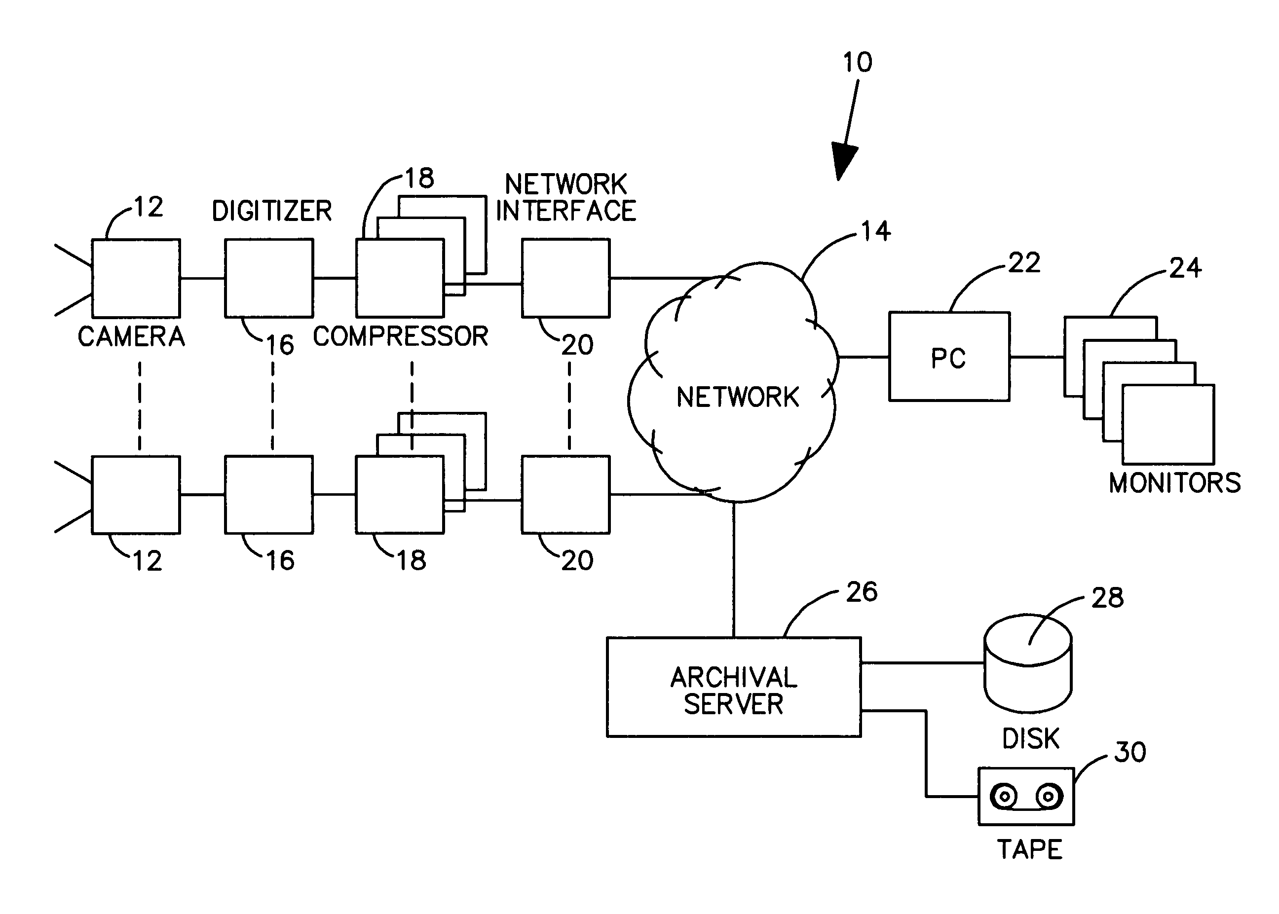
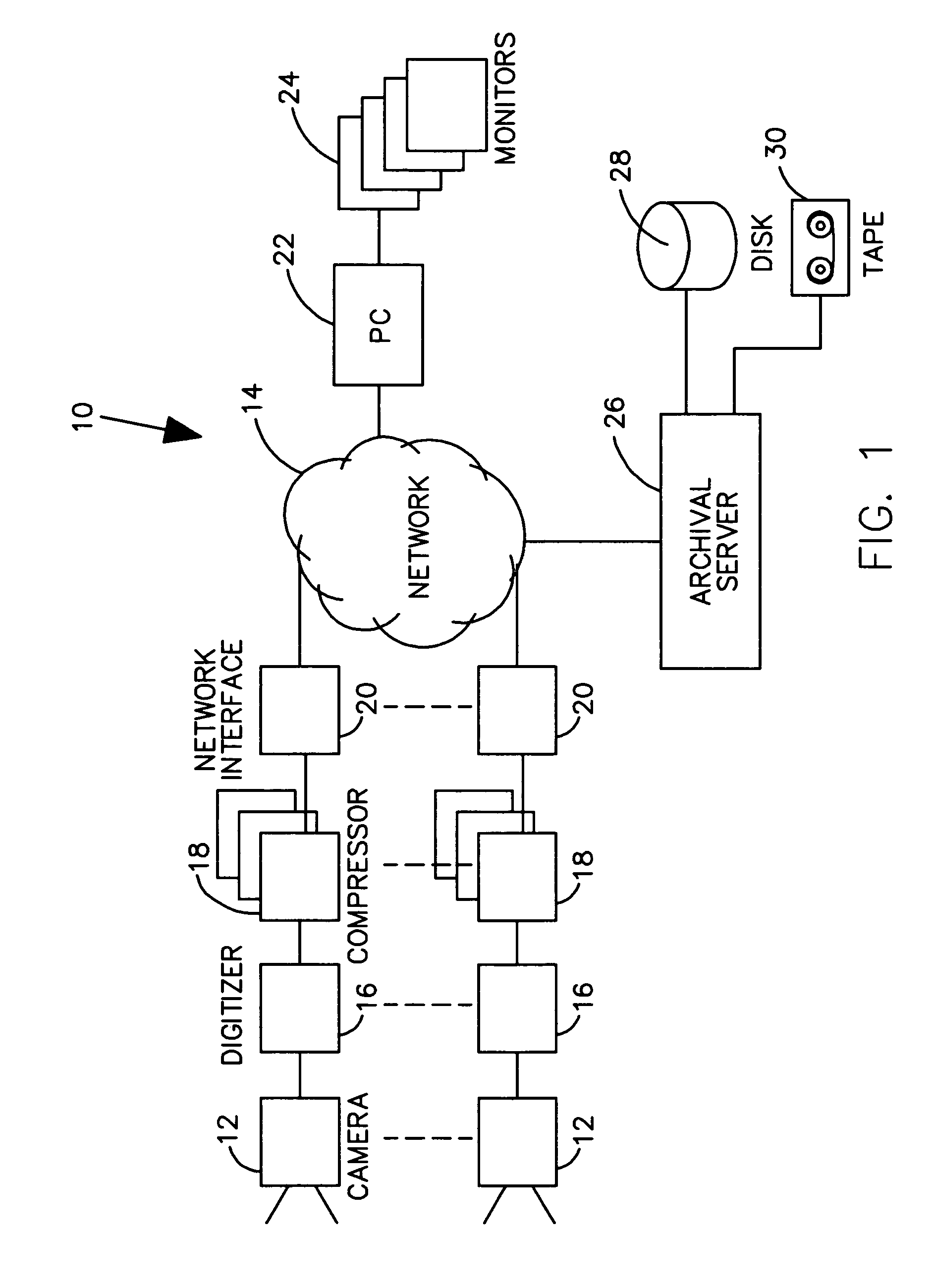
[0040]Referring now to FIG. 1, a system 10 contains a camera or a plurality of video cameras 12 operable via a common network 14. These cameras 12 are disposed around a location or locations to be monitored. Each camera produces a video signal representing a scene of interest. The video signal is digitized by digitizer 16, compressed by compressor(s) 18, and transmitted to the network 14 via network interface 20. The network may be a data network such as the Internet or a private network. In a preferred embodiment of the present invention, multiple compressors 18 are employed in each camera to compress the captured image into a plurality of different compressed signals, each representing different degrees of image resolution, region of interest within the camera view, filtered or masked data from the camera view, compression type, or compressed bit rate. These multiple video streams may be combined into one composite stream for network transmission, or may be maintained as separate ...


PUM


Abstract

A camera system comprises a camera that produces a video signal, a video compressor that compresses the video signal, a system control processor that passes the compressed video signal, and a network interface that receives the compressed video signal, wherein the video compressor comprises configurable parameters that affect a bandwidth of the compressed video signal.

Description

CROSS-REFERENCE TO RELATED APPLICATIONS[0001]The present invention is a Continuation-In-Part of and claims priority from patent application Ser. No. 09 / 715,783 now abandoned, filed on Nov. 17, 2000, titled MULTIPLE VIDEO DISPLAY CONFIGURATIONS AND BANDWIDTH CONSERVATION SCHEME FOR TRANSMITTING VIDEO OVER A NETWORK, from patent application Ser. No. 09 / 725,368 now abandoned, filed on Nov. 29, 2000, titled MULTIPLE VIDEO DISPLAY CONFIGURATIONS AND BANDWIDTH CONSERVATION SCHEME FOR TRANSMITTING VIDEO OVER A NETWORK, from patent application Ser. No. 10 / 266,813 filed on Oct. 8, 2002 now abandoned, titled ENHANCED APPARATUS AND METHOD FOR COLLECTING, DISTRIBUTING, AND ARCHIVING HIGH RESOLUTION IMAGES, from pending patent application Ser. No. 10 / 776,129 filed on Feb. 11, 2004 U.S. Pat. No. 7,576,770, titled SYSTEM FOR A PLURALITY OF VIDEO CAMERAS DISPOSED ON A COMMON NETWORK and from patent application Ser. No. 10 / 971,857, filed on Oct. 22, 2004 now abandoned, titled MULTIPLE VIDEO DISPLAY ...

Claims


Application Information

Patent Timeline
Patent Type & Authority Patents(United States)
IPC IPC(8): H04N7/18
CPCH04N5/144H04N5/232H04N5/23206H04N7/181H04N21/234H04N21/4223H04N21/4516H04N21/64769H04L65/80H04N23/661H04N23/651H04N23/631H04N23/635H04N23/695
Inventor METZGER, RAYMOND R.BAIRD, JOHN M.MONROE, DAVID A.
Owner PR NEWSWIRE
Why Eureka
Try Eureka