Two-dimensional position sensor

a position sensor and two-dimensional technology, applied in the field of two-dimensional position sensors, can solve the problems of high cost, physical space and complexity, and high cost of circuit connections, and achieve the effects of reducing the resistance of the path, reducing the amount of conductive materials, and reducing the capacitive coupling

a position sensor and two-dimensional technology, applied in the field of two-dimensional position sensors, can solve the problems of high cost, physical space and complexity, and high cost of circuit connections, and achieve the effects of reducing the resistance of the path, reducing the amount of conductive materials, and reducing the capacitive coupling

US7808255B2Inactive Publication Date: 2010-10-05NEODRON LTD

Image

  • Two-dimensional position sensor
  • Two-dimensional position sensor
  • Two-dimensional position sensor

Examples


Embodiment Construction

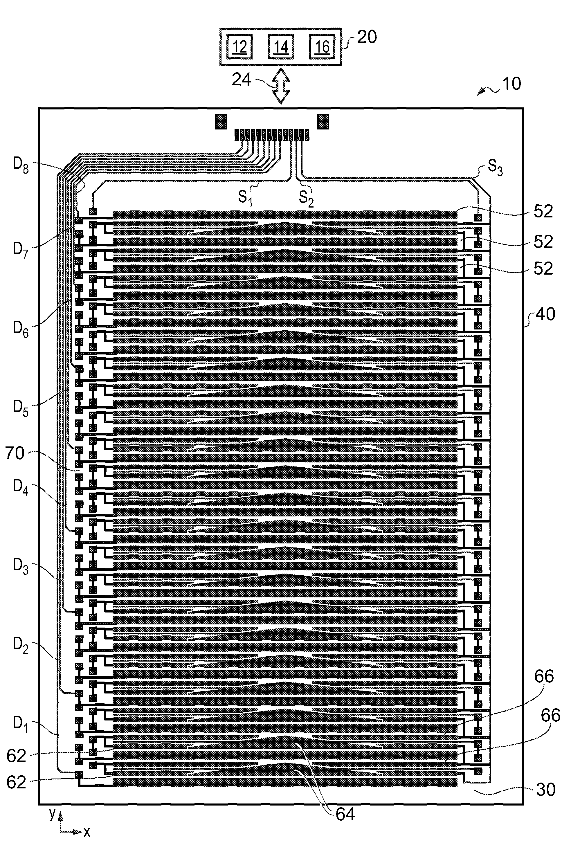
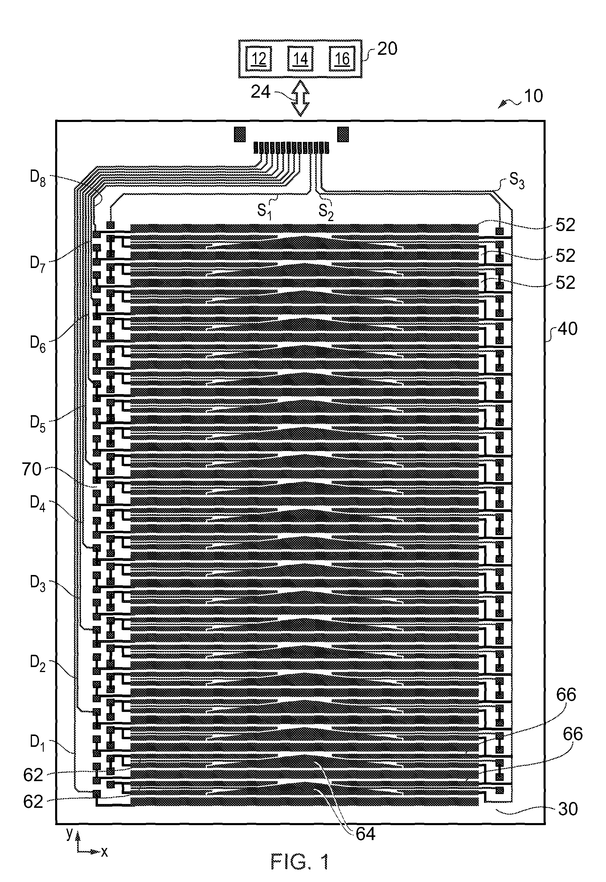
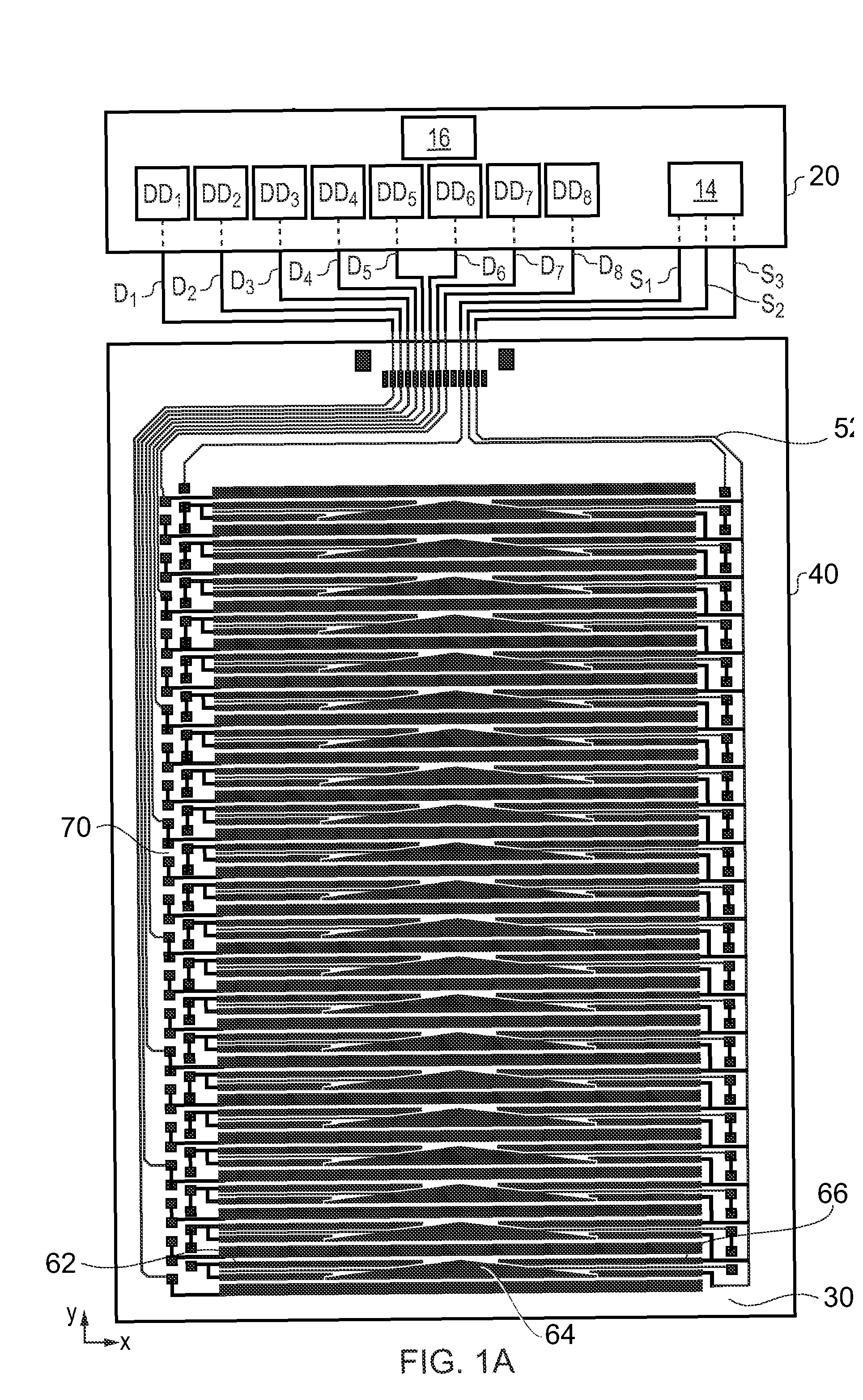
[0040]FIG. 1 is a view of a front side of a position sensor 10 according to an embodiment of the invention. The front side of the position sensor is typically the side facing the user during normal use of the sensor or an apparatus incorporating the sensor. The sensor 10 comprises a substrate 40 bearing an electrode pattern 30 defining a sensitive area of the sensor and a controller 20. The controller 20 is coupled to electrodes within the electrode pattern by a connection 24. The electrode pattern is on one side of the substrate, typically on the opposite side of the substrate from the side facing the user during normal use.

[0041]The electrode pattern 30 on the substrate 40 can be provided using conventional techniques (e.g. lithography, deposition, or etch or deactivation techniques). The substrate is of a dielectric material such as a plastics film, in this case Polyethylene Terephthalate (PET). The electrodes comprising the electrode pattern are of a transparent conductive mater...


PUM


Abstract

A two-dimensional position sensor is formed by drive electrodes (52) and sense electrodes (62, 64, 66) both extending in the x-direction and interleaved in the y-direction. The sense electrodes comprise several groups, two of which co-extend in the x-direction over each different portions of extent in the x-direction. The drive and sense electrodes are additionally arranged to capacitively couple with each other. In use, drive signals are applied to the drive electrodes and then the resultant sense signals received from the sense electrodes measured. The position of a touch or stylus actuation on the sensor is determined in the x- and y-directions as follows. In the x-direction, the position is determined by an interpolation between sense signals obtained from co-extending pairs of sense electrodes, and in the y-direction by interpolation between sense signals obtained from different sequences of drive signals applied to the drive electrodes.

Description

BACKGROUND OF THE INVENTION[0001]The invention relates to 2-dimensional position sensors. More particularly the invention relates to 2-dimensional position sensors of the type based on capacitive proximity sensing techniques. Such sensors may be referred to as 2-dimensional capacitive transducing (2DCT) sensors. 2DCT sensors are based on detecting a disturbance in a capacitive coupling of sensor electrodes, either to ground or to another electrode, caused by the proximity of a pointing object. A measured location for the disturbance corresponds to a measured position for the pointing object.[0002]2DCT sensors are typically actuated by a human finger, or a stylus. Example devices include touch screen and touch sensitive keyboards / keypads, e.g. as used for controlling consumer electronic devices / domestic appliances, and possibly in conjunction with an underlying display, such as a liquid crystal display (LCD), or cathode ray tube (CRT). Other devices which may incorporate 2DCT sensors...

Claims


Application Information

Patent Timeline
05 Oct 2010
Publication
US7808255B2
IPC
G01R27/26; G06F3/045
CPC
G06F3/044; G06F3/0446; H03K17/962; G06F3/0448
Inventors
HRISTOV, LUBEN; SLEEMAN, PETER T