Signal transmission apparatus and signal reproduction apparatus using a rotary transformer

a technology of transmission apparatus and transformer, which is applied in the direction of digital recording, magnetic tape recording, instruments, etc., can solve the problems of limiting the improvement of the rotary transformer, the limitation of the bandwidth in the reproduction of the original, and the increase of the cost of mass production, so as to achieve the effect of wide bandwidth, increased cost, and high transfer ra

Inactive Publication Date: 2005-03-15
SONY CORP
View PDF7 Cites 0 Cited by
  • Summary
  • Abstract
  • Description
  • Claims
  • Application Information

AI Technical Summary

Benefits of technology

It is an object of the present invention to provide a signal transmission apparatus using a rotary transformer by which a wide bandwidth and a high transfer rate can be used without a significant increase of the cost.
With the signal transmission apparatus, since the passive element circuit including the inductance element is provided additionally to the output stage of the rotary transformer to broaden the band to the higher frequency side, a higher frequency signal (or signal component) can be transmitted, and consequently, a higher transfer rate of a system can be achieved. Besides, the effects just described can be achieved without the necessity to increase the coupling coefficient or decrease the inductance for the rotary transformer, but only it is necessary to additionally provide the passive element circuit described above. Therefore, no significant rise of the cost is involved. Naturally, also where a rotary transformer which is improved in terms of the coupling frequency or the inductance is used, there is an advantage that further increase of the bandwidth can be achieved if the configuration of the present invention is applied.
With the signal reproduction apparatus, since the signal transmission apparatus described above is applied, it is possible to transmit a higher frequency signal than ever. Consequently, the signal reproduction apparatus can cope with recording of a higher density and so forth. Further, since the restriction to the bandwidth by the rotary transformer is moderated, the band of the reproduction system can be extended to the higher frequency side to sufficiently secure the reproduction band at a high transfer rate and reduce the error rate.

Problems solved by technology

The conventional circuit, however, has the following problem where it is tried to increase the bandwidth and the transfer rate.
In particular, the conventional circuit is disadvantageous in that, for example, where a magnetic resistive (MR) element is used as a head or in a like case, the bandwidth in reproduction is limited principally by the rotary transformer, more particularly by the inductance, coupling coefficient, floating capacitance and so forth of the rotary transformer.
However, for example, if it is tried to raise the coupling coefficient, then this has a bad influence in that the cost upon mass production rises.
Therefore, the methods mentioned are restricted in improvement of the rotary transformer.

Method used


Image

  • Signal transmission apparatus and signal reproduction apparatus using a rotary transformer
  • Signal transmission apparatus and signal reproduction apparatus using a rotary transformer
  • Signal transmission apparatus and signal reproduction apparatus using a rotary transformer

Examples


Embodiment Construction

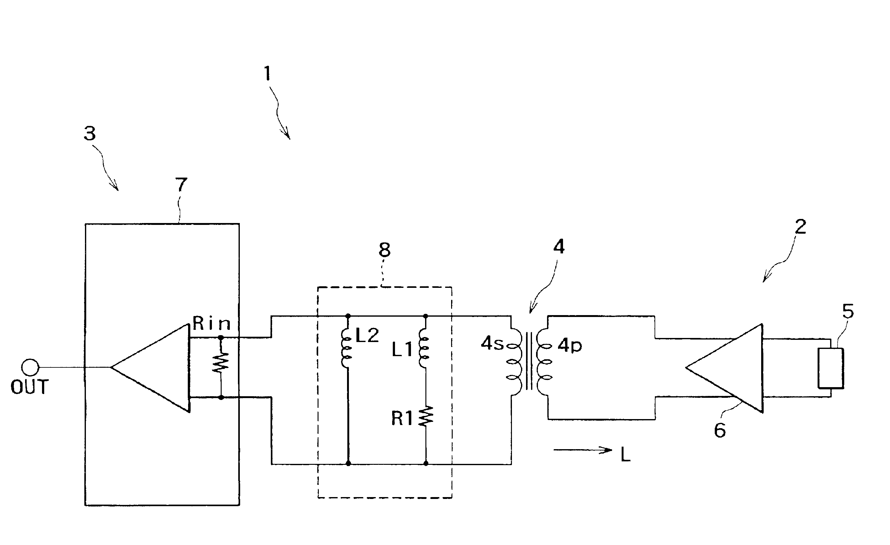
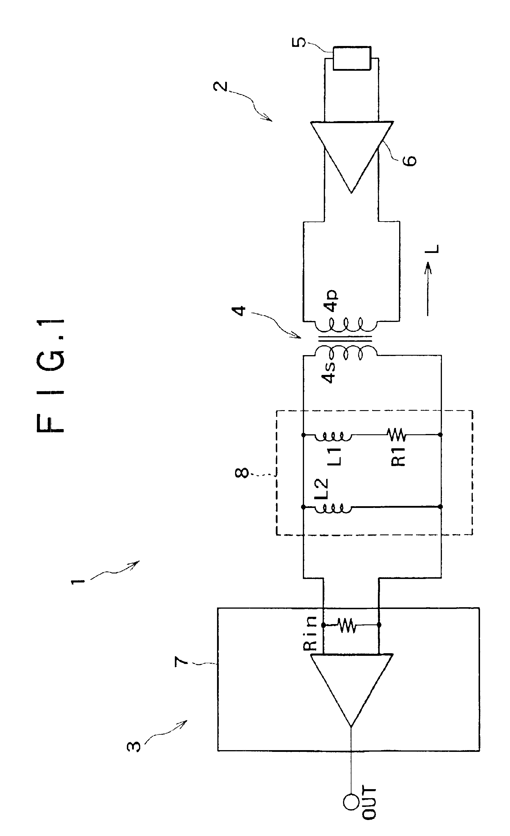
Referring first to FIG. 1, there is shown a configuration of a signal transmission apparatus to which the present invention is applied. The signal transmission apparatus 1 shown includes a transmission side circuit 2 and a reception side circuit 3 connected, that is, electro-magnetically coupled, to each other by a rotary transformer 4.

It is to be noted that a rotary transformer is used typically, in a magnetic recording and / or reproduction apparatus in which a rotary head is used. Thus, the signal transmission apparatus 1 shown in FIG. 1 is formed as a circuit of a signal reproduction system of a magnetic recording and / or reproduction apparatus.

A reproduction head 5 and a reproduction amplifier 6 which compose the transmission side circuit 2 are provided on the rotor side such that an output signal of the reproduction amplifier 6 is transmitted to the reception side circuit 3 provided on the stator side through the rotary transformer 4. It is to be noted that the reproduction head ...


PUM

PropertyMeasurementUnit
frequencyaaaaaaaaaa
inductanceaaaaaaaaaa
equivalent inductanceaaaaaaaaaa

Abstract

The invention provides a signal transmission apparatus using a rotary transformer by which a wide bandwidth and a high transfer rate can be used without a significant increase of the cost. The signal transmission apparatus includes a transmission side circuit and a reception side circuit between which a rotary transformer is interposed. A passive element circuit including an inductance element is connected to an output stage of the rotary transformer in parallel to the transformer. The passive element circuit has an inductance value set substantially equal to or lower than an equivalent inductance value when the circuit of the rotary transformer side is viewed from the reception side circuit.

Description

RELATED APPLICATION DATAThe present invention claims priority to Japanese Application No. P2001-236236 filed Aug. 3, 2001, which applications incorporated herein by reference to the extent permitted by law.BACKGROUND OF THE INVENTIONThis invention relates to a technique for allowing a wide band and a high transfer rate to be used in a signal transmission apparatus and a signal reproduction apparatus in which a rotary transformer is used.An apparatus is known which uses a rotary transformer as signal transmission means for transmitting a signal from a rotary system. For example, in a magnetic recording and / or reproduction apparatus in which a rotary head is used or a like apparatus, a rotary transformer is used in a circuit which transfers a reproduction signal from the rotor side to the stator side. In the circuit of the type described, the band is limited by the inductance of the magnetic head and the rotary transformer. In this regard, a reproduction amplifier is disposed on the s...

Claims


Application Information

Patent Timeline
Patent Type & Authority Patents(United States)
IPC IPC(8): G11B5/008G11B5/00G11B5/53G11B5/02G11B7/00H01F38/14
CPCG11B5/00G11B5/0086G11B2005/0016G11B7/00G11B5/53
Inventor SUZUKI, KYOKO
Owner SONY CORP
Why Eureka
Try Eureka