Check patentability & draft patents in minutes with Patsnap Eureka AI!

Fuel cell having end cell with bypass passage

a fuel cell and bypass technology, applied in the field of fuel cells, can solve the problems of reducing power generation efficiency and gas supply, and achieve the effect of limiting the inflow of water

Active Publication Date: 2020-01-28
TOYOTA SHATAI KK
View PDF9 Cites 0 Cited by
  • Summary
  • Abstract
  • Description
  • Claims
  • Application Information

AI Technical Summary

Benefits of technology

This design effectively suppresses water inflow into power generation cells, maintaining gas supply efficiency and preventing power generation efficiency reduction by ensuring water is drawn into the end cells, where it can be carried away, thus enhancing overall fuel cell performance.

Problems solved by technology

This reduces the amount of gas supplied to the membrane electrode assembly and thus may decrease the power generation efficiency.

Method used


Image

  • Fuel cell having end cell with bypass passage
  • Fuel cell having end cell with bypass passage
  • Fuel cell having end cell with bypass passage

Examples


Embodiment Construction

[0018]A fuel cell according to one embodiment will now be described with reference to the drawings.

[0019]First, the schematic configuration of the fuel cell will be described.

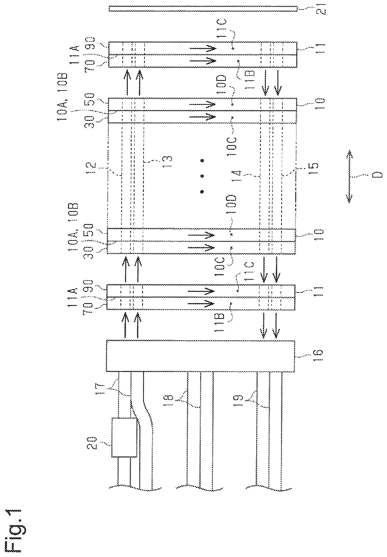
[0020]As shown in FIG. 1, the fuel cell includes stacked power generation cells 10 and a pair of end cells 11 provided at positions sandwiching the power generation cells 10 in a stacking direction D (the lateral direction in FIG. 1). The fuel cell of the present embodiment has 330 power generation cells 10. The fuel cell of the present embodiment is installed as a power source in an electric vehicle.

[0021]The fuel cell has in it a hydrogen gas introducing conduit 12 and an air introducing conduit 13. The hydrogen gas introducing conduit 12 distributes and introduces hydrogen gas to each power generation cell 10 and each end cell 11. The air introducing conduit 13 distributes and introduces air to each power generation cell 10 and each end cell 11. The fuel cell also has in it a hydrogen gas discharging conduit...


PUM

PropertyMeasurementUnit
pressure lossaaaaaaaaaa
poweraaaaaaaaaa
temperatureaaaaaaaaaa

Abstract

A fuel cell includes power generation cells and an end cell. Each power generation cell has in it a gas passage, through which power generation gas passes. The fuel cell includes an introducing conduit, which distributes and introduces the power generation gas into the gas passages, and a discharging conduit, which merges flows of the power generation gas after passing through the gas passages and discharges the merged flow. The end cell has in it a bypass passage, which connects the introducing conduit and the discharging conduit to each other. The bypass passage is composed of parallel channels, each of which is independently connected to the introducing conduit. The parallel channels include lower parallel channels and upper parallel channels. The pressure loss in each of the lower parallel channels is smaller than the pressure loss in each of the upper parallel channels.

Description

BACKGROUND OF THE INVENTION[0001]The present invention relates to a fuel cell that is composed of stacked cells.[0002]Power generation cells of a polymer electrolyte fuel cell each include a membrane electrode assembly (so-called MEA) and a pair of separators sandwiching the membrane electrode assembly. The membrane electrode assembly has an electrolyte membrane made of an ion-exchange membrane and a pair of electrodes sandwiching the electrolyte membrane. Then, fuel gas (for example, hydrogen gas) is supplied to a gas passage formed between one of the pair of separators and the membrane electrode assembly, and oxidation gas (for example, air) is supplied to a gas passage formed between the other separator and the membrane electrode assembly.[0003]Typically, a fuel cell is configured by stacking a plurality of power generation cells together. The fuel cell has in it an introducing conduit, which distributes and introduces a power generation gas to the gas passages of the power gener...

Claims


Application Information

Patent Timeline
Patent Type & Authority Patents(United States)
IPC IPC(8): H01M8/0258H01M8/04291H01M8/241H01M8/2483H01M8/2457H01M8/0202H01M8/0247
CPCH01M8/04291H01M8/2483H01M8/0258H01M8/241H01M8/0247H01M8/0202H01M8/2457Y02E60/50
Inventor KONDO, TAKASHIHASHIMOTO, KEIJI
Owner TOYOTA SHATAI KK
Features
  • R&D
  • Intellectual Property
  • Life Sciences
  • Materials
  • Tech Scout
  • Unparalleled Data Quality
  • Higher Quality Content
  • 60% Fewer Hallucinations
Learn More